ISO 10211:2007 Thermal bridges in building construction. Test case A.3 validation - QuickField simulation example
QuickField validation of the test case A.3 presented in ISO 10211:2007 Thermal bridges in building construction.
How to find thermal bridge heat flow iso 10211 case a.3?
Engineering answer Typical applications Geometry
Given
Task
Solution
Results
Thermal coupling coefficients (reference values are in the brackets).
To comply with the ISO 10211:2007 the difference between calculated and reference heat flux should be less than 2% (0.1°K - for temperature). This simulation accuracy complies with the requirements of ISO 10211:2007.
Engineering question
Set up a 3D QuickField Steady-state Heat Transfer problem for ISO 10211 case A.3 thermal bridge validation and evaluate heat flow from computed field results.
building thermal bridges, wall junction regions, structural insulation junctions
Download
Simulation problem
Problem Type
3D problem of heat transfer.
Thermal conductivity of materials:
AAC λ1 = 0.7 W/K-m.
Insulation λ2 = 0.04 W/K-m.
Brick λ3 = 1.0 W/K-m.
Concrete slab λ4 = 2.5 W/K-m.
Plaster λ5 = 1 W/K-m.
The floor slab penetrates the wall near the corner and forms the cold bridge. Determine the flux and the thermal coupling coefficients.
Air contact surface thermal resistance Rs is caused by the convection. The convection coefficient value is reciprocal to the surface resistance value:
α = 1 / Rs [W/(K·m²)].
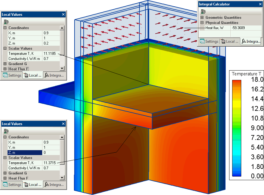
Temperature distribution in media (click to see 3D view):
Temperature in the corners:
QuickField
Reference
%%
First floor
11.12°C
11.11°C
<0.1 K
Second floor
11.37°C
11.32°C
<0.1 K
Heat flux:
59.4 W
59.98 W
1%
External
First floor
Second floor
External
(1.000)
(0.000)
(0.000)
First floor
0.375 (0.378)
0.401 (0.399)
0.223 (0.223)
Second floor
0.329 (0.331)
0.216 (0.214)
0.455 (0.455)
Video
Related examples
*ISO 10211:2007(en) Thermal bridges in building construction - Heat flows and surface temperatures - Detailed calculations.