Three phase transformer losses
QuickField simulation example
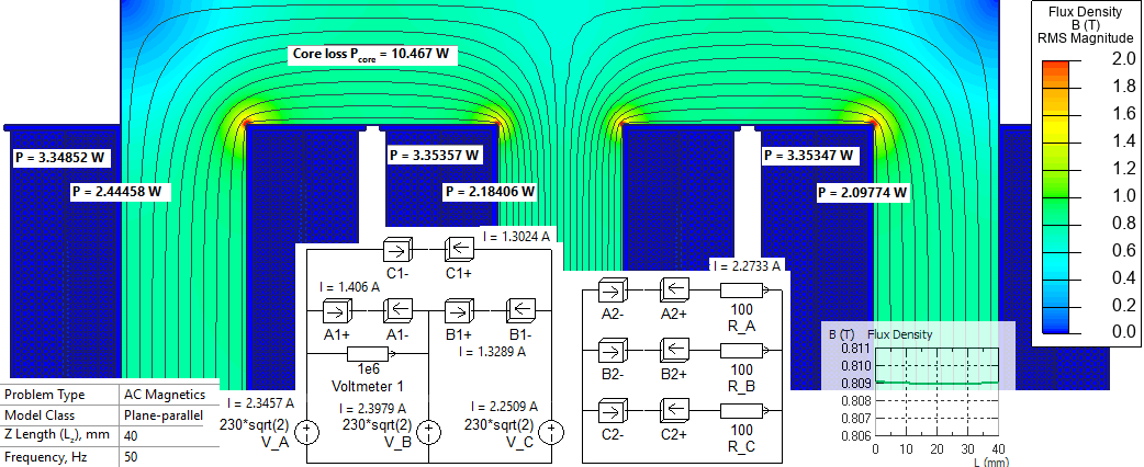
The transformer has a primary voltage of 400 V and a secondary voltage of 220 V, with a delta (Δ) to wye (Y) connection scheme. Its rated power is 1600 W. Details of the winding configuration and load conditions are provided in the accompanying circuit diagram. Both electrical and magnetic losses are calculated. These losses are used as input for the temperature distribution analysis.
Problem Type
Plane-parallel problem of AC magnetics
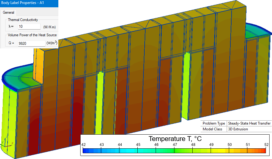
3D problem of Heat transfer
Geometry
Model z-length is 40 mm.
Given
Primary winding ø1.5 mm x 972 turns,
Secondary winding ø2 mm x 567 turns,
Frequency f=50 Hz, rated load 3x100 Ohm.
Copper conductivity σ=56 MS/m.
Core permeability μ = 1000, core loss Cm = 1.5 W/kg at f=50 Hz and B=1.5 T.
Core steel density ρ = 7650 kg/m³.
Ambient air temperature is +20°C, convection coefficient on the external surfaces of the transformer is 5 W/K*m².
Task
Calculate the magnetic and electrical losses in the three-phase transformer, and use the resulting loss power to determine the temperature distribution.
Solution
Only the core and two 40mm-length parts of the winding (e.g. A1+ and A1-) are present in the 2D model. To account for the resistance of the parts not included in the model we reduce the conductivity of the material. This way we will calculate accurate value of the power loss in the copper.
The inductance of the winding sections located outside the core is negligible.
| Winding | Primary | Secondary |
| Average turn length, mm | 4*(46+72)/2 = 236 | 4*(77+107.4)/2 = 368.8 |
| Turn length in the 2D model, mm | 40 + 40 = 80 | 40 + 40 = 80 |
| Conductivity, MS/m | 56*80/236 = 18.98 | 56*80/368.8 = 12.15 |
Conductors are covered with the insulation. So, the effective cross-section is reduced even more:
| Winding | Primary | Secondary |
| Conductor diameter d, mm | 1.5 | 2 |
| Conductor cross-section area πd²/4, mm² | 1.767 | 3.141 |
| Insulation thickness t, mm | 0.019 | 0.020 |
| Copper area, mm² | 1.679 | 3.017 |
| Conductivity, MS/m | 18.98*1.679/1.767 = 18.0 | 12.15*3.017/3.141 = 11.67 |
QuickField uses the Bertotti core loss model. Hysteresis loss is
Physt [W/m³] = kh · B² · f
Steel manufacturer provides loss value as
Physt [W/m³] = Cm[W/kg] · ρ[kg/m³], where Cm is measured at specific conditions (B = 1.5 T, f = 50Hz).
Then the coefficient value is
kh = (Cm * ρ) / (B² · f) = (1.5*7650) / (1.5² · 50) = 102.

To calculate the temperature distribution, we solve a 3D heat transfer problem. In this model, the primary and secondary windings are represented as solid blocks with an average thermal conductivity of 10 W/(m·K) and a uniformly distributed heat source. The heat source is defined by the loss density:
q = Losses [W] / Volume [m³].
The winding losses used in this calculation are obtained from the magnetic simulation performed in QuickField. External surfaces of the transformer are cooled by natural convection with ambient air temperature 20°C and convection coefficient is 5 W/K*m².
Results
| Voltage, V | Current, A | Loss, W | Volume, cm³ | Losses density, W/m³ | |
|---|---|---|---|---|---|
| Primary | 400 | 2.35, 2.40, 2.25 | 4.88, 4.36, 4.2 | 492 | 9920, 8860, 8540 |
| Secondary | 227 | 2.27 | 6.7 | 776.7 | 8630 |
| Core | - | - | 10.5 | 1696 | 6190 |
Reference:
* http://en.wikipedia.org/wiki/Transformer
- Video: Three phase transformer losses. Watch on YouTube.
- Download simulation files (files may be viewed using any QuickField Edition).