Power transmission line transposition - QuickField simulation example
At longer power lines wires are transposed according to the transposing scheme. Each of the three conductors must hang once at each position of the overhead line. On transmission lines of 110-500 kV rate one complete cycle of a transposition should be carried out if the line length exceeds 100 km. The transposition should be carried out so that total lengths of transmission line parts were approximately equal.
How to find effect of conductor transposition in three phase transmission line?
Answer Typical applications Geometry
Given
Task
Solution
Each conductor consists of aluminum and steel wires. We do not draw individual wires and represent conductors by solid blocks.
Results
Phase conductor impedance is 19.28∠58.588° + 20.46∠54.17° + 20.17∠57.899° = 59.87 Ohm ∠57.18°
* Reference
Engineering question
Set up a plane-parallel QuickField AC Magnetics problem for a three-phase transmission line and evaluate conductor transposition effects from computed field results.
overhead transmission lines, transposed conductors, three-phase line corridors
Download
Simulation problem
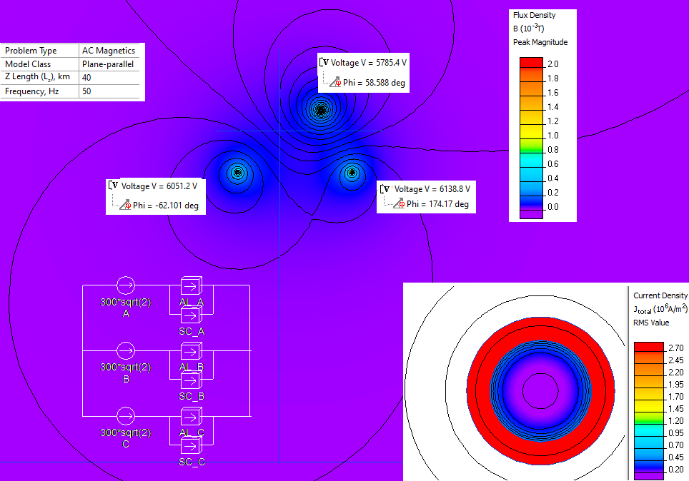
Problem Type
Plane-parallel problem of AC magnetics.
The length of transmission line is 120 km. The distance between transposition points is 40 km.
ACSR conductor* consists of 19 steel wires width diameter of 2.482 mm and 16 aluminum wires with diameter is 2.863 mm.
Aluminum conductivity is 33.5 MS/m; steel core permeability 200, steel core conductivity is 5.9 MS/m.
Rated current I = 300 A (r.m.s.), frequency f = 50 Hz.
Calculate transmission line phase inductance.
The are three 40km-long sections. In each section the phase conductors occupy different position on the tower.
In section #2 conductor A occupies the place of conductor B : ZA(#2) = ZB(#1).
In section #3 conductor A occupies the place of conductor C : ZA(#3) = ZC(#1).
Total impedance of conductor A is: ZA(#1) + ZA(#2) + ZA(#3) = ZA(#1) + ZB(#1) + ZC(#1).
So we model only section #1 and calculate impedance of each phase conductor ZA(#1), ZB(#1), ZC(#1).
Phase
Current, A
Voltage drop, V
Impedance, Ohm =
= Voltage drop / Current
A
300∠0°
5785.4∠58.588°
19.28∠58.588°
B
300∠120°
6138.8∠174.17°
20.46∠54.17°
C
300∠-120°
6051.2∠-62.101°
20.17∠57.899°
Phase conductor inductance is LA = LB =
LC = 59.87*sin(57.18°) / 2πf = 0.160 H per 120 km of the transmission line length.
Brahma, ACSR Aluminum Conductor Steel Reinforced
Video
Related examples