Electric field stress in the transformer oil
QuickField simulation example
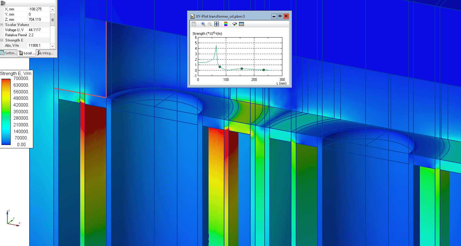
The transformer is submerged in the oil. The windings are insulated by the oil-impregnated paper. We need to locate the places with high electric stress (in addition to the well-known areas between windings and between windings and core).
Problem Type electrostatics.
Geometry 3D extrusion.
Given
Relative permittivity of oil εr = 2.2,
Relative permittivity of pressboard εr = 4.5,
High voltage (phase) V = 6 kV (RMS).
Low voltage (phase) V = 0.4 kV (RMS).
Tank, core are grounded (zero electric potential).
Task
Calculate the electric field stress distribution in the oil.
Solution
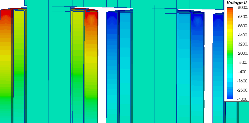
We simulate the static problem (fixed moment of time), when phase A has maximum electric potential V*cos(0°), potentials of the phases B and C: V*cos(120°) and V*cos(240°) respectively. Electric potential is distributed linearly along the coil (maximum value is at the top, zero value is at the bottom of the winding).
Results
Electric potential distribution along the windings:
Electric field stress in the oil (coils, core are hidden):
- Video: Electric field stress in the transformer oil. Watch on YouTube
- Download simulation files (files may be viewed using any QuickField Edition).