Bushing insulator - QuickField simulation example
A set of 10kV-rated bushing insulators is installed on the transformer tank lid.
How to find electric field in transformer bushings?
Answer Typical applications Geometry 3D extrusion.
Given
Task
Solution ResultsEngineering question
Set up a 3D QuickField Electrostatics problem for a transformer bushing insulator and evaluate electric field distribution from computed field results.
transformer bushings, oil-air insulation interfaces, high-voltage insulation assemblies
Download
Simulation problem
Problem Type electrostatics.
Relative permittivity of oil ε = 2.2,
Relative permittivity of insulator ε = 6,
Line-to-line ULL = 10 kV.
Find the maximum field strength at the insulator and the electric field distribution.
To find the maximum field strength it is enough to simulate the electrostatic field at the moment of maximum voltage at the specific phase insulator.
This simulation represents the specific moment in time when the Phase A voltage is at its peak (ωt = 0).
The line-to-line voltage must be converted to phase voltage for the calculation
UA = ULL·√2/√3 · cos(ωt) = 10000 · 0.8165 · cos(0) = +8165 V,
UB = 10000 · 0.8165 · cos(120) = -4082 V,
UC = 10000 · 0.8165 · cos(240) = -4082 V.
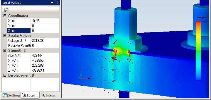
Electric field strength distribution at the surfaces of the insulators is presented at the picture below.
Video
Related examples