Capacitive voltage divider - QuickField simulation example
Capacitive voltage divider is used to reduce the voltage level to a measurable value. It consists of a high voltage electrode, a grounded electrode and a terminal that is connected to a voltmeter. Voltage divider can be used for DC, AC and transient voltage measurements. The maximum allowed voltage is 400 kV. Our task is to calculate the electric field stress distribution and the voltage at the output terminal. Divider features rotation symmetry, so it can be represented by the 2D axisymmetric model.
How to find voltage distribution in capacitive dividers?
Answer Typical applications Geometry
Given
Task
Solution
Results
Reference
Engineering question
Set up an axisymmetric QuickField Electrostatics problem for a capacitive voltage divider structure and evaluate voltage distribution from computed field results.
capacitive voltage dividers, high-voltage probes, measurement divider assemblies
Download
Simulation problem
Problem Type
Axisymmetric problem of electrostatics.
Relative permittivity of media: Melinex 3.2, PVC 4, ultra-high-molecular-weight polyethylene (UHMWPE) 2.3.
Peak voltage is 400 kV.
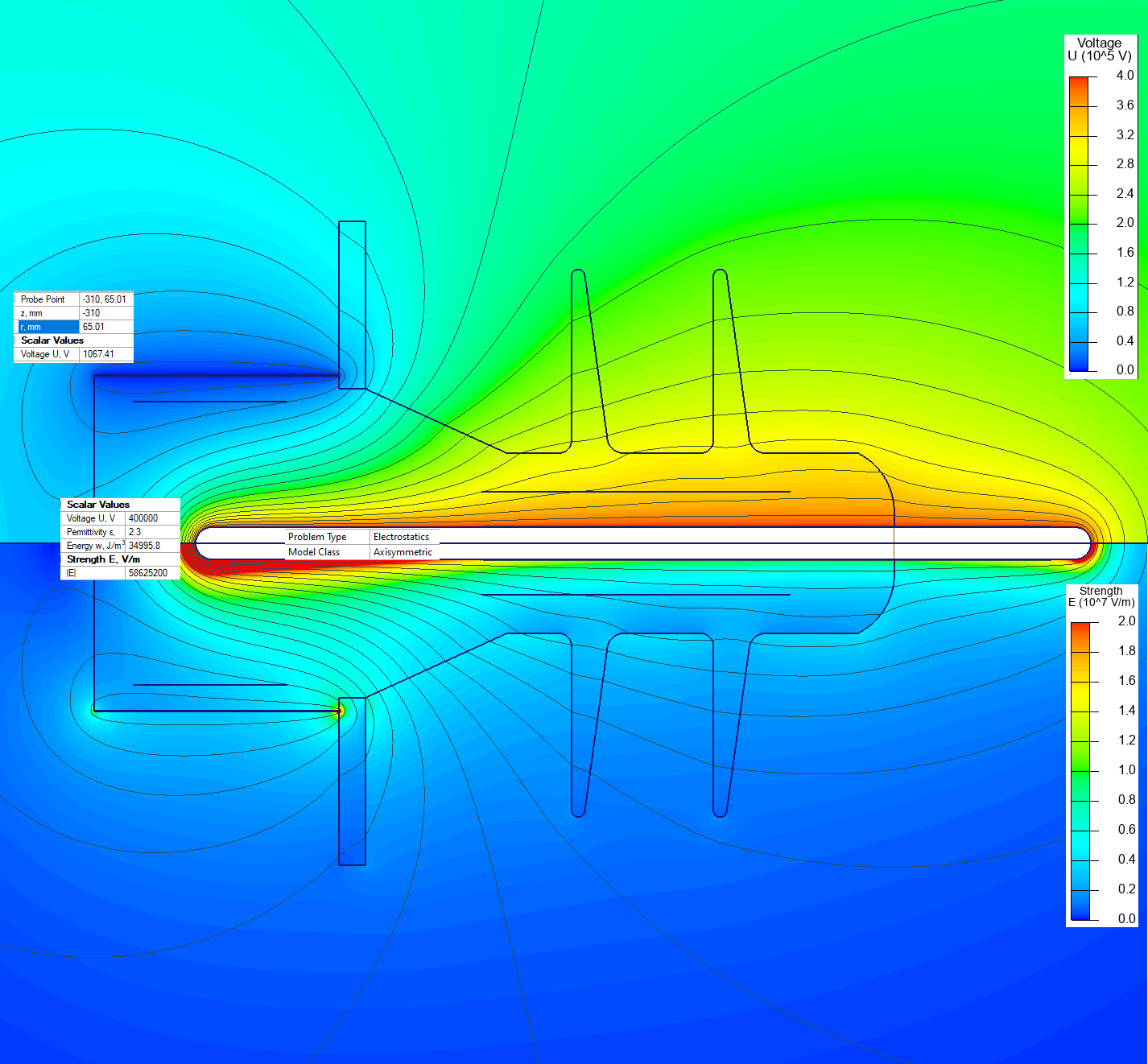
Calculate the electric field stress distribution and voltage on the output terminal of the capacitive divider when 400kV pulse is applied.
Since we are interested only in the peak value of the electric field stress, we can simulate the electrostatic problem instead of the transient electric problem.
Floating conductor boundary condition is assigned to the voltmeter terminal.
Electric field stress at the electrode tip is 58 kV/mm, which is below the maximal allowable stress value of 70 kV/mm [1].
Voltmeter terminal electric potential is 1.0 kV, which is within the acceptable range of the voltmeter (1.8 kV) [1].
[1] Shah, R.R.D. & Cliffe, Robert & Senior, Peter & Novac, B.M. & Smith, Ivor. (2001). An ultrafast probe for high-voltage pulsed measurements. Fuel Cells Bulletin. 1020 - 1023 vol.2. 10.1109/PPPS.2001.1001716.
Video
Related examples