Shielded microstrip transmission line capacitance
QuickField simulation example
A shielded microstrip transmission line consists of a substrate, a microstrip, and a shield.
Problem Type
Plane-parallel problem of electrostatics.
Geometry
The transmission line is directed along z-axis, its cross section is shown on the sketch. The rectangle ABCD is a section of the shield, the line EF represents a conductor strip.
Model depth Lz = 1 m.
Given
Relative permittivity of air ε = 1;
Relative permittivity of substrate ε = 10.
Task
Determine the capacitance of a microstrip transmission line.
Solution
There are several different approaches to calculate the capacitance of the line:
- Apply some distinct potential to the strip and calculate the charge that arises on the strip;
- Describe the strip as having constant but unknown potential and charge it with some distrinc value, then measure the potential that arises on the strip.
Results
Electric field strength distribution in a microstrip transmission line. Approach 1.
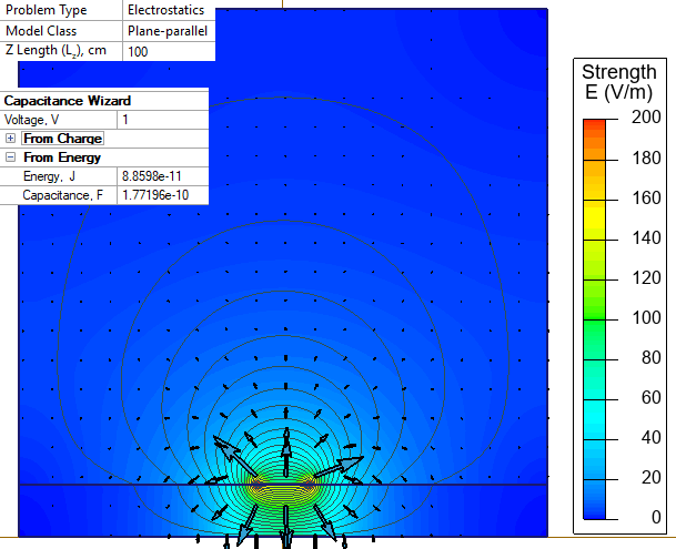
| Theoretical result [1] (model depth L = 1 m.) | C = 178.074 pF. |
| Approach 1. C = q/U | C = 178.36 pF |
| Approach 1. C = 2*W/U² | C = 177.196 pF |
| Approach 2. C = q/U | C = 178.31 pF) |
| Approach 2. C = 2*W/U² | C = 177.191 pF |
Reference
[1] Ostergaard, D. F. (1987). Adapting available finite element heat transfer programs to solve 2-D and 3-D electrostatic field problems. Journal of Electrostatics, 19(2), 151–164.
- Video: Microstrip line. Watch on YouTube
- View simulation report in PDF
- Download simulation files (files may be viewed using any QuickField Edition).