End winding insulation - QuickField simulation example
The insulation material at the winding ends is often subjected to higher voltages than other parts of the winding. Solid
insulation is used to subdivide long oil gaps into smaller ones.
How to find electric field stress in transformer end-winding insulation?
Answer Typical applications Geometry
Given
Task
Solution
Results
Engineering question
Set up a plane-parallel QuickField AC Conduction problem for transformer end-winding insulation and evaluate electric field stress from computed field results.
transformer end-winding insulation, transformer terminal insulation, power transformer winding ends
Download
Simulation problem
Problem Type
Axisymmetric problem of AC conduction.
Relative permittivity of oil 2.2
Relative permittivity of paper 3.5
Relative permittivity of pressboard 4.5
Winding voltage = 200 kV (r.m.s.);
Static end ring (SER) voltage = 200 kV (r.m.s.);
Frequency f = 50 Hz.
Oil dielectric strength 20 kV/mm.
Calculate electric field stress distribution in the oil gaps.
In QuickField we should specify peak voltage value, which is 200000*sqrt(2) V.
Dielectric conductivity is very low, comparing to the conductivity of the steel core. Zero conductivity is specified for all dielectric materials.
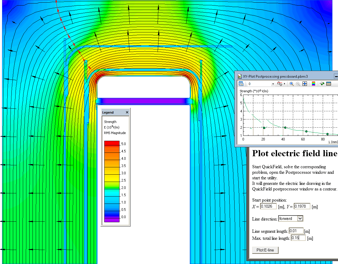
Electric field lines tool is used to construct XY-plot along the E-line.
Electric stress distribution and electric potential lines.
Video
Related examples