Four-probe sheet resistance measurement - QuickField simulation example
Four-probe method is used to measure the thin sheet resistance. This method is similar to a Wenner array method. But here we deal with a limited in size specimen. So the corrections to the equation should be made [1]. We use a finite element model to verify these equations.
How to find four-probe sheet resistance measurement?
Answer Typical applications Geometry
Given
Task
Solution
Four-point probe equation for surface resistivity is ρs = (V / I) * C(a/d;d/s), where C(2;10) = 4.2357 in accordance with [1].
Results
Reference
Engineering question
Set up a plane-parallel QuickField DC Conduction problem for a four-probe electrode arrangement and evaluate sheet resistance from computed field results.
four-probe resistivity samples, thin conductive sheets, semiconductor wafers
Download
Simulation problem
Problem Type
Plane-parallel problem of DC conduction.
d = 100 mm, a = 200 mm, s = 10 mm.
Surface electric resistance of the film is Rs = 10 Ω/square, film thickness is t = 200 nm.
Electrodes spacing s = 20 mm, injected current I = 4.5 mA.
Calculate the electric potential difference between electrodes 1 and 2.
For the film we should specify electrical conductivity, which is reciprocal to the product of surface resistance and the film thickness: σ = 1/(Rs*t) = 1/ (10 * 200e-9) = 0.5 MS/m.
The electrode conductivity is much higher than that of the film. We model electrodes by specifying their electric potentials and current density on the electrode surfaces.
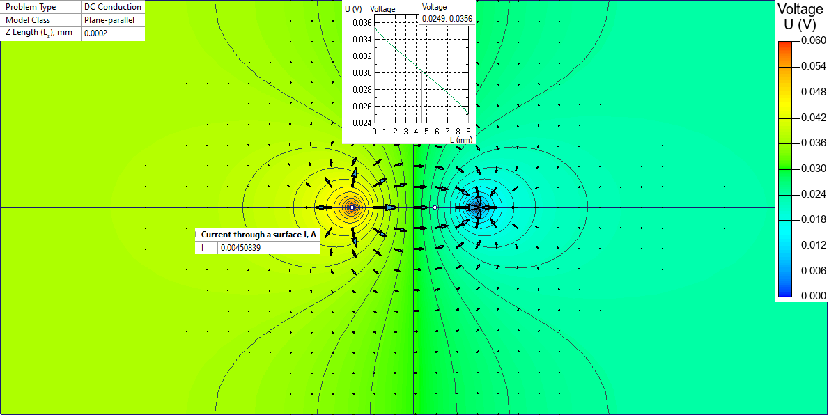
Electrode tip diameter is 1 mm. In QuickField we specify current density at (I+) electrode 0.0045 / (PI*0.001/2) / 200e-9. At the (I-) electrode we specify zero electric potential. Electrodes (1) and (2) are floating conductors.
Potential difference between electrodes 1 and 2 is 0.0356-0.0249 = 0.0107 V. Following the analytical equation the resistivity is ρs = (0.0107/0.0045)*4.2357 = 10.07 Ω/square. This shows that the finite element simulation result agrees with the analytical approach with 0.7% tolerance.
F. M. Smits Measurement of sheet resistivities with the four-point probe, The Bell System Technical Journal, vol. 37, no. 3, pp. 711-718, May 1958.
Related examples