Stratified high voltage bushing
QuickField simulation example
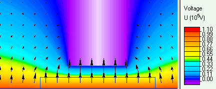
Stratified high voltage bushing is composed of several insulation layers separated with very thin "floating" conductors. Their constant but unknown potential results from the capacitive distribution of electrostatic field and may be controlled by variation of their lengths, thickness and permittivity of the dielectric layers. From the technological point of view only the lengths adjustment can be considered as reasonable way of getting the most uniform distribution of radial component Er of electric strength. It assures the best utilization of insulating material and moderates the field across the high voltage bushing.
In theory, the infinite number of free potential electrodes leads to the uniform and continuous distribution of electric field across the bushing (E(r)=const) instead of logarithmic one. In reality, only the finite number of layers can be considered, usually 10-12.
The main goal of the example is to model very simple (only 2 layers) high voltage bushing, find the E(r) distribution and compare results with some mathematical formula. The condition of Ermax equality in every layer (E1rmax = E2rmax) gives the possibility to find the length of "floating" conductor and their potential.
Problem Type
An axisymmetrical problem of free potential electrode in electrostatic field. Dirichlet boundary conditions with given potential are placed at zero and high voltage electrodes.
Geometry of the high voltage bushing:
zero potential tubular electrode
______________________________________
                   | |
     air           | |<-- barrier
                   | | (zero pot. electrode)
                   |_|
                  /   \ <--  2-nd ins. layer
                 /__2__\ <-- "floating" electrode
                /       \ <-- 1-st ins. layer
_______________/____1____\______________
high voltage tubular electrode

_ _ _ _ _ _ _ _ _ _ _ _ _ _ _ _ _ _ _ _
axis of rotational symmetry
All dimensions are in centimeters. The length (L) of "floating" electrode is to be calculated before the modelling of the bushing arrangement.
- the radius of zero pot. electrode r3 = 30 cm
- the radius of the hole in the barrier r2 = 6 cm
- the radius of "floating" electrode r1 = 4 cm
- the radius of high voltage electrode r0 = 2 cm
Given
The relative permittivity of dielectric material (epoxy resin) is assumed as 5.0 and high voltage potential - 110 kV.
In order to be closer with mathematical description of the model, the slope of dielectric edge was considered as perpendicular to the axis of symmetry.
Results of field calculations:
- Three capacities: C1, C2 - of the layers and C10 - the free potential electrode-to-ground are calculated by means of integrals (stored energy or surface charge). The condition of charge balance Q1 = Q2 + Q10 leads to the equation for determining the length (L) of free potential electrode.
zero potential tubular electrode ____________________________________ | | | | | | |_____| | | | | === C10 C2-->| === | | __|__|__|__| | | | | === C1 | __________|_____|_____|_____________ high voltage tubular electrode _ _ _ _ _ _ _ _ _ _ _ _ _ _ _ _ _ _ axis of rotational symmetry - The max. value of E(r) along the middle-cross section of the bushing is found from the "XY-plot" option. It is recommended to notice the E1rmax and E2rmax equality.
- The potential U of "floating" electrode is found by means of "Average surface potential" calculation or by "Local Value" tool.

C10[pF] C1[pF] C2[pF] Er1[kV/cm] Er2[kV/cm] U[kV] Theory 3.84 84.64 68.51 36.57 36.57 59.31 QF_1 3.97 81.37 70.10 30.97 31.16 57.51 QF_2 3.52 79.68 75.90 - - - Remarks:
1. Two ways of determining the capacity value in QuickField were applied. QF_1: from the energy of electrical field (2·W / U²), QF_2 from the total charge at the electrode (Q/U).
2. The difference with theoretical results is caused mainly by limited number of nodes of the QuickField Student Edition.
- View simulation report in PDF
- Download simulation files (files may be viewed using any QuickField Edition).