Linear induction motor - QuickField simulation example
Simulate transients in the winding of a linear induction motor (LIM) when feeding with pulse-width modulated voltage.
How to find linear induction motor pwm winding currents?
Answer Typical applications Geometry
Given Task
Solution
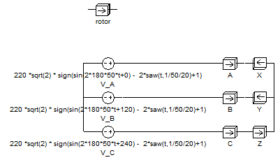
Power supply circuit of LIM windings using PWM:
Results
Engineering question
Set up a plane-parallel QuickField Transient Magnetics problem for a linear induction motor winding and evaluate PWM currents from computed field results.
PWM-fed linear motors, inverter-driven linear motors, transient motor winding systems
Download
Simulation problem
Problem Type
Plane-parallel problem of Transient magnetics.
Relative magnetic permeability of stator steel μ = 1000;
Relative magnetic permeability of rotor steel μ = 500;
Relative magnetic permeability of conductors, insulation and air μ = 1;
Electrical conductivity of the rotor σ = 10 MS/m;
Electrical conductivity of winding conductors σ = 56 MS/m;
Voltage U = 220 V (r.m.s.), frequency f = 50 Hz;
Modulation frequency fm = 1 kHz.
Calculate current vs. time in the winding.
Phase shifts in the windings are determined by the classical way for three-phase power supply φ = 0, 120 and 240 degrees.
Law of PWM signal formation in time is determined by the formula:
U*sqrt(2) * sign (sin(2*180*f*t+ φ) - 2*saw(t, 1/fm)+1)
To visualize PWM signal you can use the formula plotter.
Integration is carried out until time = 0.02 sec, with time step = 0.00013 sec;
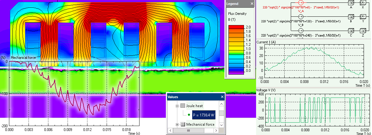
Flux density distribution and rotor eddy losses at t=0.01s after start.
Phase current, rotor force contains higher harmonics. Using a harmonic analyzer, it turns out that the current unity harmonic magnitude is 21 A, the total harmonic distortion is 8%.
Related examples