Potential transformer electric stress - QuickField simulation example
Potential transformer or voltage transformer* is an instrument transformer used to measure the high voltage. The primary high voltage winding has a large number of turns and features a special form factor to reduce the electric field stress.
How to find electric stress distribution in transformer winding?
Answer Typical applications Geometry
Given
Task
Solution
Results
* Reference
The primary high voltage winding has a large number of turns and features a special form factor to reduce electric field stress. One end of the winding is connected to the mains and the other end is grounded. The electric potential is distributed linearly along the winding. There are 35000 turns in the primary winding and 100 turns in the secondary.
Engineering question
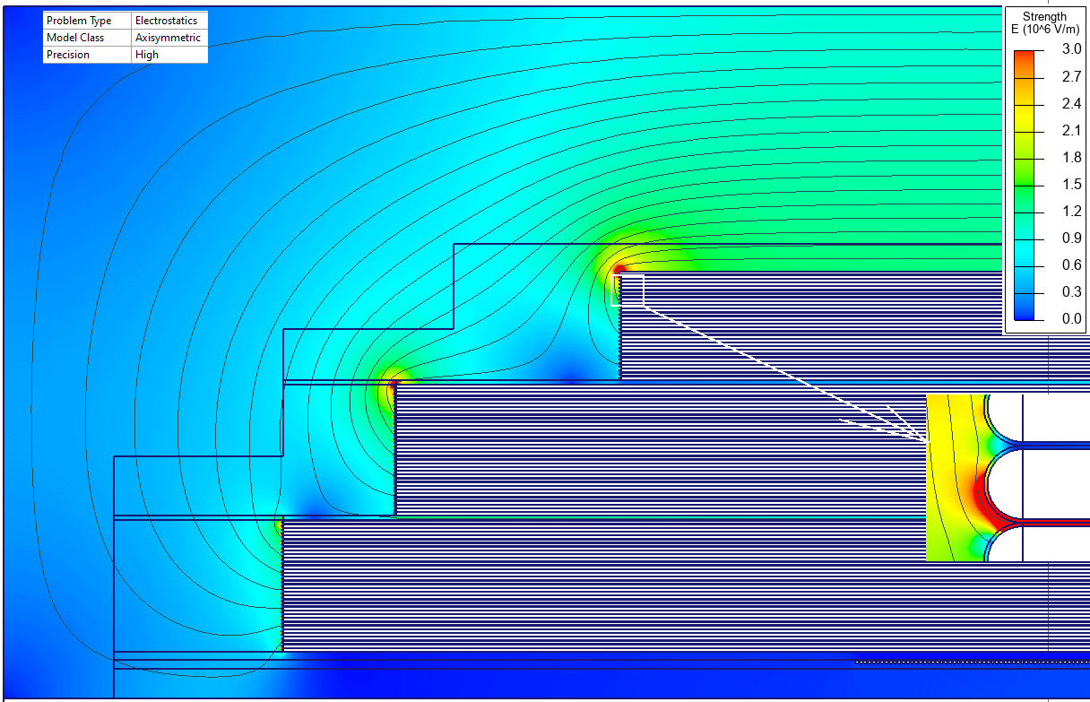
Set up an axisymmetric QuickField Electrostatics problem for a potential transformer winding and evaluate electric stress distribution from computed field results.
instrument transformers, voltage transformer windings, transformer insulation systems
Download
Simulation problem
Problem Type
Axisymmetric problem of Electrostatics.
High voltage is 35 kV. Transformation ratio is 350:1.
Dielectric permittivity of media: oil 2.3, paper + oil 2.3, cardboard 2, conductor insulation 3.
Calculate the electric stress distribution.
The electric potential is linearly distributed along the primary winding. We do not draw each individual conductor. Instead we draw each individual layer and specify the electric potential as a function of coordinates.
The transformer operates at AC voltage. We simulate a single moment of time, when the voltage value is equal to 35 kV. So, we use the Electrostatics module of QuickField.
The most stressed part is the insulation between the adjacent winding layers. The stress value there is 10 kV/mm.
Wikipedia: Voltage transformer
Video
Related examples