Schlumberger array
QuickField simulation example
In this example the soil features three layers with different resistivity. We use the Schlumberger array method to measure the apparent value of soil resistivity.
First we test the Schlumberger array method with the homogeneous soil model with the resistivity of 100 Ohm*m. This way we will be able to compare the actual soil resistivity value with the value calculated by the Schlumberger array method.
Then we change the soil resistivity to a three layered model and run the analysis again.
Problem Type
3D problem of DC conduction.
Geometry
Given
Probe electrodes spacing is a = 40 cm. Distance from the voltage probe to the current probe electrodes is c = 130 cm. Electrodes are buried into the ground by b = 5 cm.
Task
Calculate the soil resistivity using the Schlumberger array.
Solution
The Schlumberger array* method uses the following equation to calculate soil resistivity:
ρ = (ΔV / I) * π* c * (c + a) / a
where I is the current injected by the current probe electrodes V+ and V-);
ΔV = V2 - V1 is a voltage drop between voltage probe electrodes.
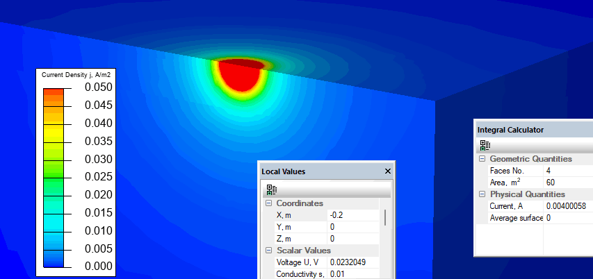
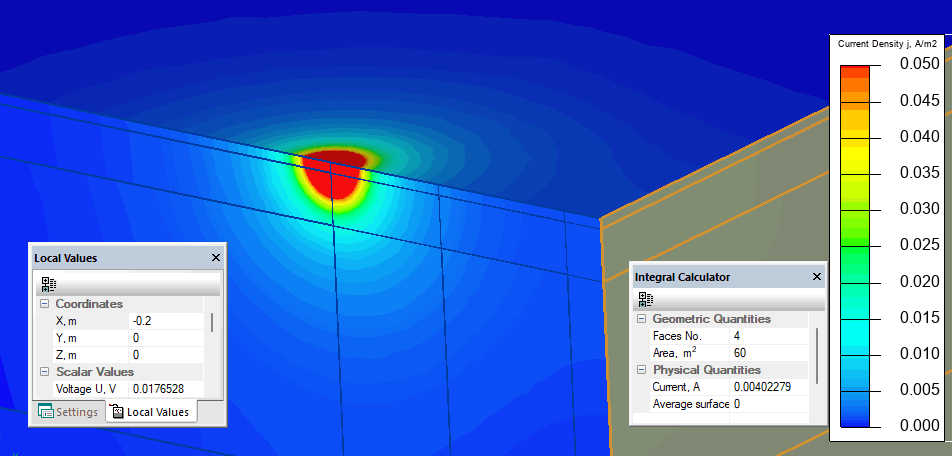
The electrode diameter is small compared to the distances between electrodes so the electrode is modelled as an edge. Electric potentials ±10 V are specified on current probe electrodes. QuickFied calculates current density and potential distribution in the soil.
Geometry model features symmetry so we reduce the simulation domain. Remember to take this fact into account when computing currents and voltages.
Results
| Current probe electrode I | Voltage probe electrode ΔV | Calculated resistivity by the Schlumberger array method | |
| Homogeneous soil
ρ=100 Ohm*m | 2*0.00400 A | 2*0.0232 V | 100.7 Ohm*m |
| Three layered soil
ρ1=100 Ohm*m ρ2=80 Ohm*m ρ3=25 Ohm*m | 2*0.00402 A | 2*0.0176 V | 76 Ohm*m |


Reference
*Wikipedia Soil resistivity, Schlumberger method.
- Download simulation files (files may be viewed using any QuickField Edition).