Submarine power cable - QuickField simulation example
A three phase submarine power cable is buried in the sea bed.*
How to find currents and field above submarine power cable?
Answer Typical applications Geometry
Given
Task Solution
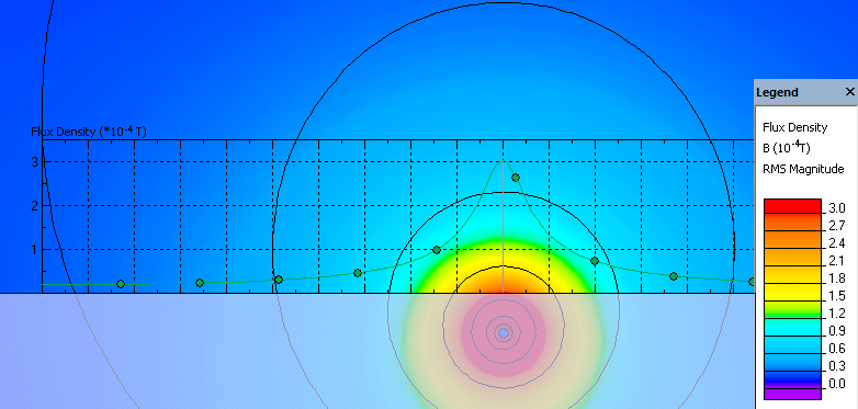
Result Magnetic flux density in the water above the cable does not exceed 0.3 mT (root mean square value).
Reference
Engineering question
Set up a plane-parallel QuickField AC Magnetics problem for a submarine power cable and evaluate currents and field above the cable from computed field results.
submarine power cables, offshore transmission cables, subsea power lines
Download
Simulation problem
Problem Type
Plane-parallel problem of AC magnetics
Cable length is 10 km.
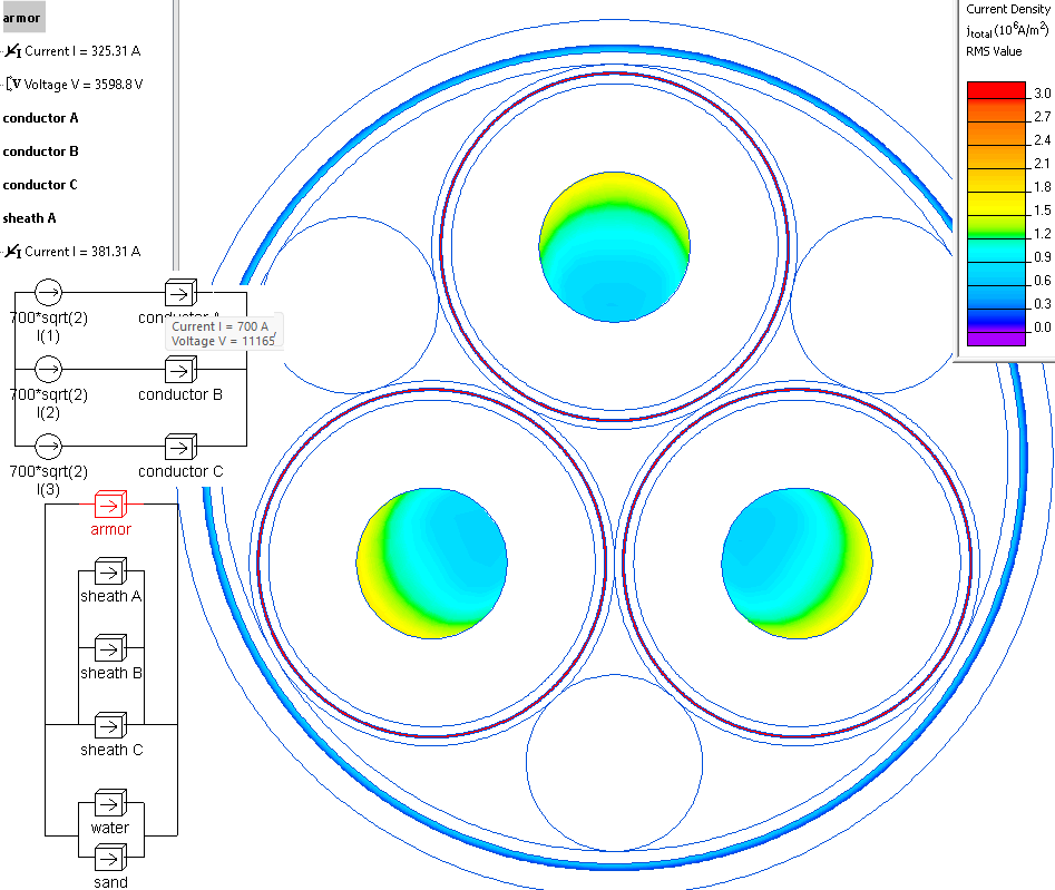
Conductor current (r.m.s. value) I = 700 A, frequency 50 Hz.
Media conductivity: copper 58 MS/m, lead 5 MS/m, steel 1.1 MS/m, sea water 5 S/m, sand 1 S/m.
Armor (steel wire) relative magnetic permeability 300.
Calculate the currents in the sheaves and armour and the magnetic flux density in the water above the cable.
Real cable includes many thin layers of semiconducting tape, used to eliminate local electric field disturbances, caused by the conductor surface irregularities. In this example we do not study these irregularities, the conductors are modelled as solid bodies with smooth surfaces, so the semiconducting layers are simulated as a part of main insulation.
In QuickField we should specify the peak values of currents that are √2 times more than r.m.s. values.
The armor and sheaths are grounded on each side and thewater and the sea-bed provide the natural return path for the currents. The conductor's connection is specified in the electric circuit.
Induced current in the sheath is 381 A, induced current in the armor is 325 A. Voltage drop in phase conductor is 11.1 kV per 10 km.
*The idea of this example is inspired by the paper: Andrew B Gill, Yi Huang, Joe Spencer, and Ian Gloyne-Philips Electromagnetic Fields emitted by High Voltage Alternating Current Offshore Wind Power Cables and interactions with marine organisms
Related examples