Transmission line magnetic coupling - QuickField simulation example
Two three phase power transmission lines go side by side for 10 km. Each transmission line is formed by 3 parallel aluminum conductors 1 cm diameter each placed on the same height above the ground (flat formation). Phase conductors in each line are separated by 1 m air clearance. Distance between the nearest conductors of two transmission lines is 18 meters.
How to find magnetic coupling between parallel transmission lines?
Answer Typical applications Geometry
Given
Task
Solution
Results
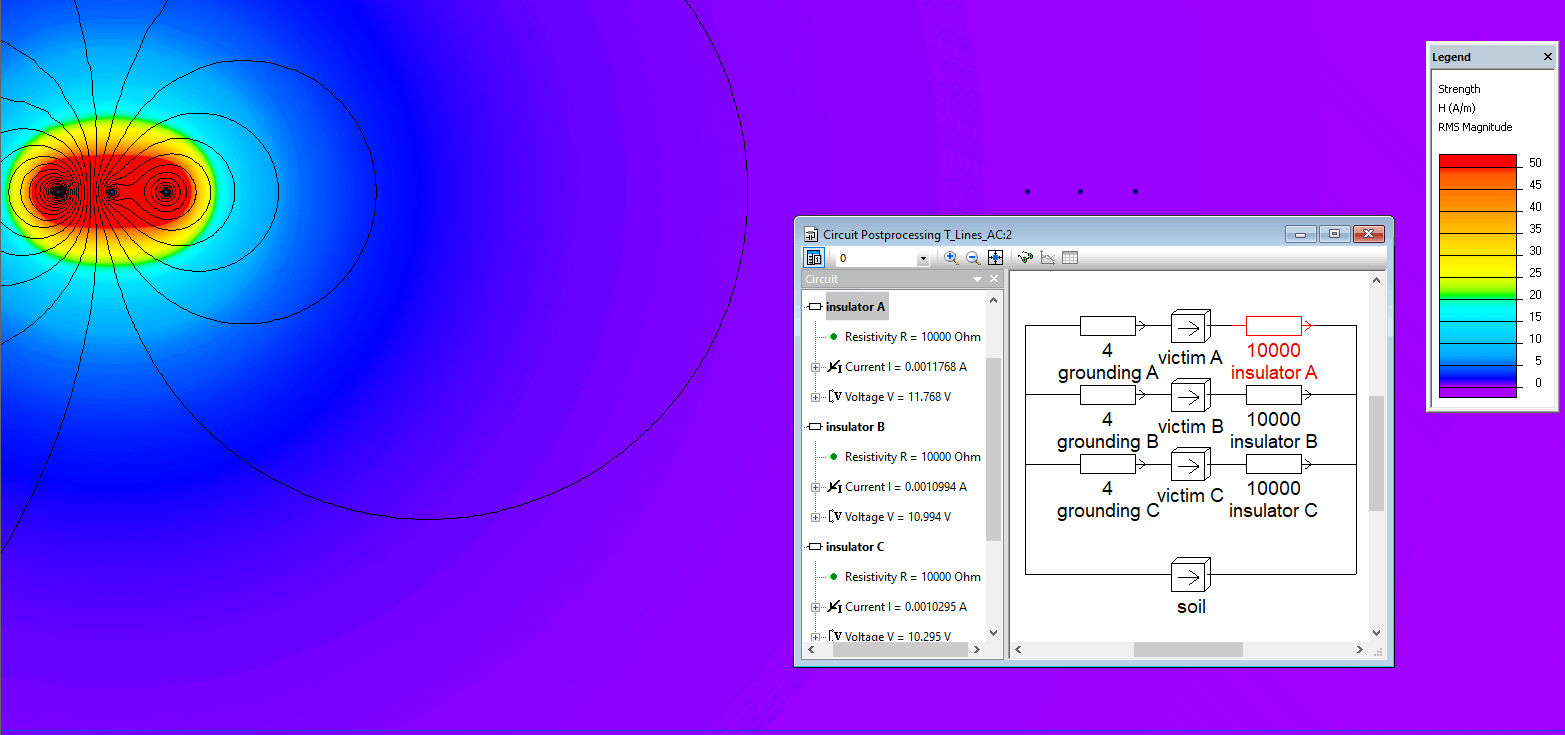
Magnetic field strength distribution in the vicinity of the victim line.
Left transmission line is energized by three phase current system. Right line is under maintenance, it is grounded at the beginning of this segment and works are performed on another end. We need to make sure that the worker is not subjected to dangerous induced voltage on the right (victim) line at normal operating conditions of the energized line.
Engineering question
Set up a plane-parallel QuickField AC Magnetics problem for parallel transmission lines and evaluate magnetic coupling from computed field results.
parallel transmission lines, overhead feeders, inductive coupling paths
Download
Simulation problem
Problem Type
Plane-parallel problem of AC magnetics.
Left line current: 200 A, root mean square (r.m.s) value
Frequency f = 50 Hz
Ground electrical conductivity σ = 0.1 S/m
Transmission line length Lz= 10 km
Victim line grounding resistance R = 4 Ohm
Find the electromagnetically induced voltages in the right (victim) transmission line at the ungrounded end of the 10 km segment.
In QuickField we should specify the peak values of currents that is √2 times more than r.m.s. value.
Phase-to-ground inductively induced voltages for victim transmission line conductors
VA = 12.2 V, VB = 11.5 V, VC = 10.8 V
Values are below the dangerous levels, so the worker is safe.
Video
Related examples