Adding vertices to 3D model
A new button Insert Vertices is added to the toolbar of the 3D Model Editor for the models created by the geometry import from CAD programs. Pressing this button turns on the vertices insertion mode. Keyboard hotkey INS works as a switch between the insert and regular modes. When the Insert mode is turned on the cursor changes its shape to crosshair.
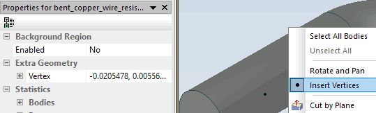
If the insert mode is on, and the cursor is over the highlighted face or highlighted edge, new vertices are created by clicking the left mouse button. List of all new vertices is displayed Extra Geometry section of the Properties window. It is possible to remove any new vertex by pressing the X button next to it, or change its coordinates. Coordinates may be edited individually or as a group, and finalized by pressing the Enter key. The list in the Extra Geometry shows the values entered by user, but the actual vertex coordinates may be adjusted to keep the vertex on the same face or edge where it was originally created. Actual coordinates of extra vertices are displayed in the Properties window in the Selection / Vertex/ Coordinates section when this vertex is selected.
Extra vertices are usually used to fine tune the mesh density distribution. To achieve this the need mesh step may be assigned to the extra vertex. Extra vertex may also have a label and a boundary condition or field source associated with this label.
Related Topic:
Creating 3D Model by Importing
Background Region
Control of the Density of 3D Mesh