Axial flux motor back EMF - QuickField simulation example
In this example we simulate the axial flux motor in a no-load mode and measure its back EMF. As there is no current in the stator winding, we can simulate it in DC magnetics: a set of problems is simulated with different rotor positions. The flux linkage with the winding is calculated and then converted into the electromotive force.
How to find magnetic field in axial-flux PM motors?
Answer Typical applications Geometry
Given
Task
Solution
Now we have a slice converted to a topology of a conventional rotating machine. LabelMover parametric tool is used to automatically rotate the rotor by 1° and measure the flux linkage with stator windings. Then the flux linkage vs. angle dependency is converted into the induced voltage vs. time dependency:
Result
References:
Motor dimensions are taken from this paper [1]. In general case the study requires 3D magnetic analysis. We used the 2D inner rotor modeling approach [2] to convert the 3D model into a set of 2D models.
Engineering question
Set up a plane-parallel QuickField DC Magnetics problem for an axial-flux permanent magnet motor and evaluate magnetic field distribution from computed field results.
axial flux motors, electric vehicle traction motors, compact permanent magnet motors
Download
Simulation problem
Problem Type
Plane-parallel problem of DC magnetics.
Stator core height 65.5 mm, tooth height 17.2 mm,
Rotor core height 55.6 mm, permanent magnet height 6.9 mm.
Rotor angular velocity 341.88 [1/s].
Permanent magnet coercive force Hc = 890 kA/m, remanence 1.175 T.
Calculate the back EMF in the stator windings.
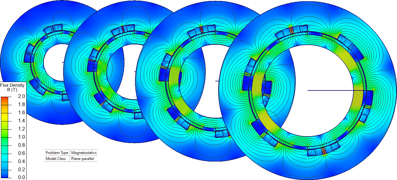
To avoid complicated 3D magnetic analysis we transform the geometry model into a number of 2D models. First, we make several circular slices, four in this case, with radii r1, r2, r3, r4. Each slice represents a dr portion of the motor.
Then we made a cut in the slice and unfold it.
Then we fold the slice to make a circle. The rotor is kept inside and the stator is kept outside. This approach is called 2D inner rotor modeling approach [2].
[1] Nadia Chaker, Ibrahim Ben Salah, Souhir Tounsi, Rafik Neji Design of Axial-Flux Motor for Traction Application. J. Electromagnetic Analysis & Applications, 2009, 2: 73-83
[2] Mehmet Gulec, Metin Aydin. Implementation of different 2D finite element modelling approaches in axial flux permanent magnet disc machines. IET Electr. Power Appl. 2018, 12, 195–202.
Related examples