Cable wall seal - QuickField simulation example
A power cable is passing through the hole in the wind turbine basement. The task is to calculate the temperature distribution.
How to find temperature near cable wall penetrations?
Answer Typical applications Geometry
Given
Task
Solution
Results
Reference
Engineering question
Represent the cable losses as volumetric heat generation in a 3D steady-state heat-transfer model and calculate the conductor and surrounding-soil temperatures.
cable wall penetrations, wind turbine cables, building cable penetrations
Download
Simulation problem
Problem Type
3D problem of heat transfer.
Cable conductor cross section is 240 mm², resistance 0.105 Ohm/km [1], current 450 A.
Thermal conductivity of materials, W/(m·K): concrete 2; copper 380; soil 0.5; resin 0.2; PVC pipe 1; sheaf 1; steel 40.
Ambient air temperature +25°C, convection coefficient 20 W/m²K.
Inside air temperature +30°C, convection coefficient 5 W/m²K.
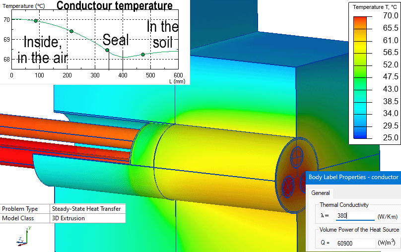
Calculate the soil temperature profile and the temperature of the cable conductor.
The cable Joule heating power Q_l = 450² * 0.105 Ohm/1000m = 21.3 W/m
In QuickField we specify the volume power density, which is Joule heating power per 1 meter of length [W/m] divided by the conductor cross-section area [m²].
Instead of drawing each strand we draw a solid conductor with a diameter of 21.1 mm as specified in the cable datasheet [1]. Cross-section area is π * 21.1² /4 = 349.67 mm².
Volume power density Q_v = 21.3 W/m / 349.67 mm² = 60.9 kW/m³.
Temperature distribution in the soil and cables.
[1] Nexans 1 x 240mm2 Versolex Orange flexible cable.
Related examples