Split core current transformer - QuickField simulation example
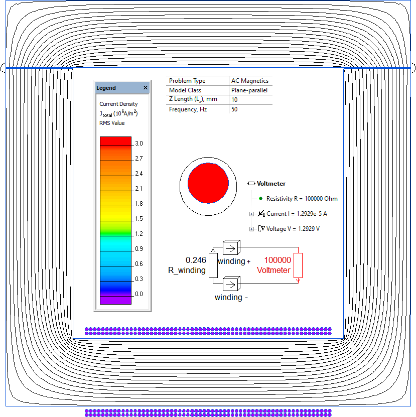
Output voltage of a split-core current transformer connected to a finite-resistance voltmeter, for the specified primary current and magnetic core..
How to find output voltage of split-core current transformers?
Answer Typical applications Geometry
Given
Task
Solution
Results
Engineering question
The winding is only partially represented in the 2D geometry model. The remaining winding length is represented by an equivalent resistor in an external electric circuit together with the voltmeter's 100 kOhm input resistance.
split-core current transformers, clamp-on current sensors, nonintrusive CT devices
Download
Simulation problem
Problem Type
Plane-parallel problem of AC magnetics.
Model z-length is 10 mm.
Input AC current is 100 A, frequency is f = 50 Hz.
Secondary winding number of turns is N= 122, conductor cross-section is Sc = 0.1964 mm², copper conductivity is σ = 58.5 MS/m.
Core permeability μ = 1000. There are 2 air-gaps at the core parts junction 0.1 mm each.
Calculate the transformer's output voltage. The inner resistance of a voltmeter is 100 kOhm.
The winding is only partially represented in the 2D geometry model. Missing parts are represented by the resistor in the electric circuit.
Average turn length is 43.2 mm. The geometry model's winding sections have a total length of (10 mm + 10 mm).
The remaining part resistance is R_winding = (1 / σ) · N · (43.2 - 10 - 10) / Sc = 0.246 Ohm.
Output voltage is 1.3 V.
Related examples