Earthing grid resistance
QuickField simulation example
IEEE 80-2013* provides an equation to calculate earthing grid resistance. The resistance depends on the total buried length of conductors LT, the apparent area of the earthing grid A and the installation depth h:
This equation does not contain grid shape parameters. Usually it is a rectangular grid with a bunch of vertical conductors installed along the perimeter of the grid. To simulate such configuration you need to run 3D DC conduction analysis, which is possible but time consuming.
In this example we choose the grid configuration so that it can be simulated in a 2D axisymmetric problem. Grid resistance is calculated and compared with the above formula.
Problem Type
An axisymmetric problem of DC conduction.
Geometry
Earthing grid consists of 6 circles with diameter 20, 30, 40, 50, 60 and 67.7 meters buried at the depth of h = 0.5 meter.
Given
Total buried length of conductors is LT = π·(20 + 30 + 40 + 50 + 60 + 67.7) = 841 m.
Apparent area of the earthing grid is A = π·67.7² / 4 = 3600 m².
Task
Calculate the earthing grid resistance.
Solution
In axisymmetric problems we consider the cross section as in the picture above. The axis of rotation is a horizontal one, so the whole picture should be rotated by 90°. Only half of the cross-section located above the axis must be included in the geometry model.
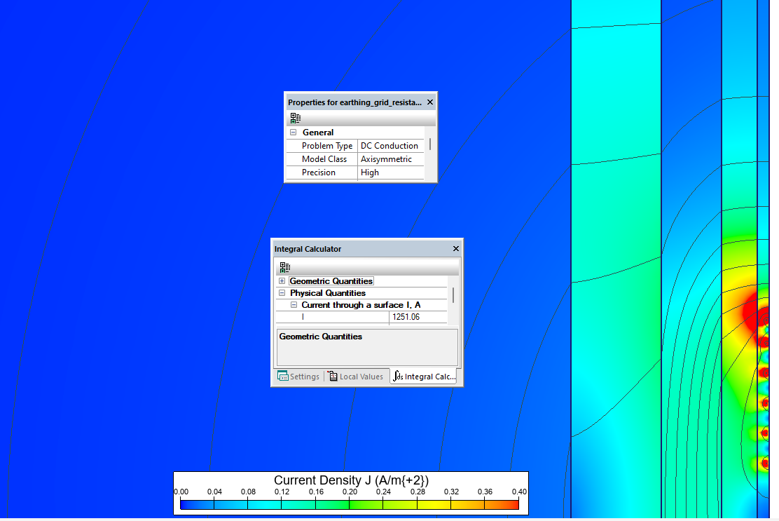
To calculate resistance we apply a test potential of 1kV to the grid electrodes and measure the current.
Two cases are simulated: the uniform soil model and the multi-layer soil model. For the uniform soil model we compare the results against the resistance value calculated by the equation above: grid resistance for uniform soil with ρ=100 Ohm*m is Rg = 0.848 Ohm.
For the multi-layer soil model we compare the results with the grounding resistance value calculated by other commercial software.
It is not possible to simulate infinitive large models. So we simulate a set of models with various dimensions to see how the current value converges.
Results
The grounding resistance depends on the distance between zero potential boundary and the ground electrode. For the distance of 1 km the ground resistance is 1000 / 1168 = 0.856 Ohm. Models with larger dimensions indicate that the earthing grid resistance might be as low as 1000 / 1228 = 0.814 Ohm.
You cannot use the simple equation with ρ=const for the earthing grid resistance calculation in the multi-layer soil model. So we compare the result with the resistance value calculated by commercial software of the rectangular grid featuring the same LT, A and h parameters as our circular grid.
| QuickField | Reference | |
|---|---|---|
| Uniform soil, ρ = 100 Ohm*m | 1000 / 1192 = = 0.839 Ohm | 0.848 Ohm* |
| Multi-layer soil | 1000 / 1251 = = 0.799 Ohm | 0.792 Ohm** |

Reference
* IEEE Std 80-2013 IEEE Guide for Safety in AC Substation Grounding,
** Multilayer earth grid resistance for 60 m square grid
- Download simulation files (files may be viewed using any QuickField Edition).