Two conductors PCB line - QuickField simulation example
This is an example of the two conductors PCB line simulation, performed with QuickField software.
How to find mutual capacitance of PCB conductors?
Answer Typical applications Geometry
The problem's region is bounded by ground from the bottom side and extended to infinity on other three sides.
Given
Task
Solution
Self capacitance: C11 = C22 = Q1 / U1 ,
Mutual capacitance: C12 = C21 = Q2 / U1 ,
where charge Q1 and Q2 are evaluated on contours around conductor 1 and 2.
Results
* Reference: A. Khebir, A. B. Kouki, and R. Mittra, An Absorbing Boundary Condition for Quasi-TEM Analysis of Microwave Transmission Lines via the Finite Element Method, Journal of Electromagnetic Waves and Applications, 1990.
Engineering question
Set up a plane-parallel QuickField Electrostatics problem for PCB conductors and evaluate mutual capacitance from computed field results.
parallel PCB conductors, multilayer PCB traces, signal routing structures
Download
Simulation problem
Problem Type
Plane-parallel problem of electrostatics.
Model depth L = 1 m.
Relative permittivity of air ε= 1;
Relative permittivity of dielectric ε= 2.
Determine self and mutual capacitance of conductors.
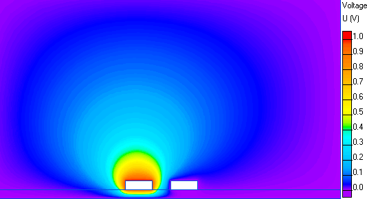
To avoid the influence of outer boundaries, we'll define the region as a rectangle large enough to neglect side effects. To calculate the capacitance matrix we set the voltage U = 1 V on one conductor and U = 0 on another one.
Potential distribution in two conductors transmission line:
C11, pF
C12, pF
Reference*
92.3
-8.50
QuickField
94.3
-8.57
Related examples