Electrolytic capacitor heating - QuickField simulation example
Electrolytic capacitor operates at DC voltage. The voltage ripple causes the ripple current that heats up the capacitor.
Engineering question
How to find temperature rise in electrolytic capacitors?
Answer Set up an axisymmetric QuickField Steady-state Heat Transfer problem for an electrolytic capacitor and evaluate temperature rise from computed field results.
Given Voltage V = 40 VDC, capacitance C = 2200 uF
Rated ripple current I = 7.2 A, AC frequency f = 100 kHz.
ESR vs. Temperature dependence
Temperature
Equivalent series resistance
20°C
0.023 Ω
125°C
0.0099 Ω
Ambient air temperature +20°C, convection coefficient 5 W/(K*m²).
Thermal conductivities of materials, W/K·m
Aluminum (can and lid)
237
Rubber
0.35
Terminals (tinned copper)
380
Electrolyte
0.21
Capacitor body*
λx = 100 λy = 0.21
Task Calculate the Joule heat loss and the temperature of the capacitor.
Solution We can approximate ESR vs. temperature dependency with linear function:
ESR(T) = 0.025495 - 0.001247 * T Joule heat losses are ESR(T) * I² = 1.32 - 0.00647 * T [W]
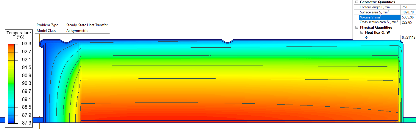
In QuickField we specify the loss density in W/m³. Capacitor body volume is 5386 mm³.
Joule heat losses density = 245000 - 1201 * T [W/m³].
There are also Ohmic losses in terminals. Terminal wire diameter is 1 mm, cross-section area is S = 0.785 mm², copper resistivity is 1.77e-8 Ohm*m. Joule heat losses density in the terminals is:
Resistivity * (I/S)² = 1.77e-8 * ( 7.2/0.785e-6 )² = 1'490'000 W/m³.
Results Capacitor Joule heat losses are 0.72 W. Capacitor internal temperature is 93°C.