Gear wheel shrink fitting - QuickField simulation example
Simulation example of the gear wheel shrink fitting. The gear wheel was heated so that its internal diameter became slightly larger than the diameter of the shaft. After mounting the gear wheel is cooled down and decreased in size.
How to find stress in gear wheel shrink fits?
Answer Typical applications Geometry
All dimensions are in millimeters.
Given
Task
Solution
Results
Engineering question
Set up a plane-parallel QuickField Stress Analysis problem for a gear wheel shrink-fit structure and evaluate stress distribution from computed field results.
gear shrink-fit assemblies, shaft-gear interference fits, mechanical press-fit joints
Download
Simulation problem
Problem Type
Plane-parallel problem of stress analysis.
Gear thickness H = 20 mm.
Gear and shaft material - steel;
Young's moduli E = 2.11*1011 N/m²;
Poisson's rations ν = 0.26;
Coefficient of thermal expansions α = 1.2*105 1/K.
Overheating temperature T = 135 °C.
Calculate the normal pressure.
The gear in the model is initially in a heated condition (already fitted to the shaft). In the properties of the gear wheel negative temperature is specified. Temperature value indicates how much the wheel has cooled. Thus, a reduction in the wheel size after fitting is simulated.
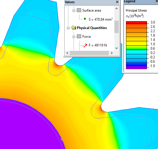
Using the integration contour, QuickField can calculate the force acting on the surface. If you draw a contour on the surface of the shaft, then the vector sum of the radial forces will be zero. To calculate the radial force we draw a contour over the surface of the shaft, using only a quarter of a circle.
Dividing the force value by the surface area, we get the normal pressure.
Radial force acting on a quarter of a circle fr = 49 kN.
Normal pressure P = fr/S = 49*10³/470*10-6 = 104 MPa.
Mechanical stress distribution in the gear wheel:
Related examples