Heat sink - QuickField simulation example
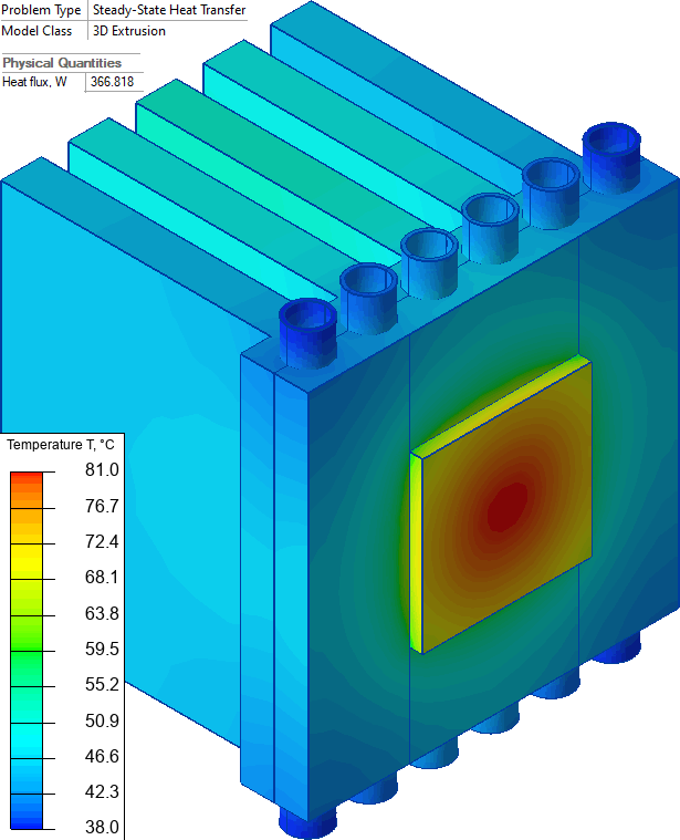
Radiator and outlet-water temperatures for a heat sink cooled simultaneously by natural air convection and flowing water under the specified heat load.
How to calculate the radiator temperature and the outlet water temperature?
Answer Typical applications Geometry
Given
Task
Solution
Water velocity* is 0.1 m/s, density 1000 kg/m³, heat capacity 4184 J/kg*°C.
Results
References:
Engineering question
Solve the 3D steady-state heat-transfer model with water-channel convection to obtain the heat-sink temperature and heat flow into the water, then calculate the outlet-water temperature rise from the absorbed heat.
electronic heat sinks, semiconductor cooling radiators, power electronics cooling devices
Download
Simulation problem
Problem Type
3D problem of heat transfer.
All dimensions are in millimeters.
Thermal conductivity of aluminum 237 W/K-m, thermal conductivity of copper 380 W/K-m.
Air convection coefficient α = 10 W/(K·m²), ambient air temperature T0 = +20 °C.
Water convection coefficient* 2500 W/(K·m²), inlet water temperature +20 °C.
Heat flux q = 70 W/cm².
Calculate the radiator temperature and the outlet water temperature.
As a first approximation we consider the water temperature to be constant along the heating channel. In fact the water heats up in the channels. The temperature rise can be calculated analytically** as ΔT = Heat flux * time / ( Water volume * density * heat capacity ), where time = channel length * velocity, and volume = channel length * cross-section area.
Heat flux that goes into the water is 366 W per 6 channels. The water temperature rise is ΔT = (366/6) * 0.1 / (19.6349e-6 * 1000 * 4184) = 0.074 °C. Our assumption that the water temperature is practically constant was correct.
* General idea of the example, water convection coefficients and model dimensions are taken from the paper by Hassan Waqas, Shan Ali Khan, Umar Farooq, Taseer Muhammad, Ahmad Alshehri & Sumeira Yasmin. Thermal transport analysis of six circular microchannel heat sink using nanofluid. Scientific Reports volume 12, Article number: 8035 (2022).
** Wikipedia Specific heat capacity
Related examples