ISO 11855-2:2015. Pipe in the floor - QuickField simulation example
This is a simulation example from ISO 11855-2:2015 Building environment design — Design, dimensioning, installation and control of embedded radiant heating and cooling systems. Part 2: Determination of the design heating and cooling capacity.
How to find underfloor cooling pipe temperature distribution iso 11855 case 1?
Answer Typical applications Geometry
Given
Task
Solution
Results
* Reference: ISO 11855-2:2015 Building environment design — Design, dimensioning, installation and control of embedded radiant heating and cooling systems — Part 2: Determination of the design heating and cooling capacity.
Engineering question
Set up a plane-parallel QuickField Steady-state Heat Transfer problem for an underfloor cooling pipe and evaluate temperature distribution from computed field results.
radiant floor cooling pipes, embedded floor pipe systems, hydronic floor cooling systems
Download
Simulation problem
Problem Type
Plane-parallel problem of Heat Transfer.
Air temperature +26°C, heat exchange coefficient at the top surface αtop = 7 W/m²K, heat exchange coefficient at the bottom surface αbottom = 11 W/m²K,
Water temperature = 18 °C, turbulent flow.
Pipe wall thickness = 2.3 mm
Thermal conductivity λ of materials:
- floor covering, 0.23 W/(m·K)
- screed, 1.2 W/(m·K)
- thermal insulation, 0.04 W/(m·K)
- concrete, 2.1 W/(m·K)
- pipe PE-X, 0.35 W/(m·K)
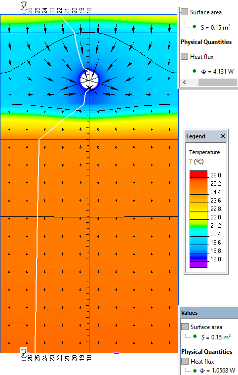
Calculate temperature distribution in the floor and heat flux at top and bottom surfaces.
Thermal resistance between water and inner pipe surface is assumed to be zero, so the fixed temperature boundary condition is used.
Average heat loss density at the top surface is 4.13 W /0.15 m² = 27.5 W/m² (ISO 11855-2:2015 gives 27.4 W/m²)
Average heat loss density at the bottom surface is 1.05 W /0.15 m² = 7.0 W/m² (ISO 11855-2:2015 gives 7.0 W/m²)
Difference between the calculated and reference values is less than 3%. This simulation accuracy complies with the requirements of ISO 11855-2:2015.
Related examples