LED PCB temperature - QuickField simulation example
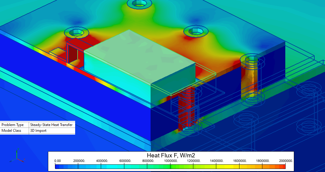
Light emitting diode is placed on the chip carrier board that is connected to the metal core printed circuit board. Thermal vias are used to provide low-resistance paths for the heat flux, helping to keep down the chip temperature.
How to find led pcb temperature distribution with thermal vias?
Answer Typical applications Geometry
Given
Task
Solution
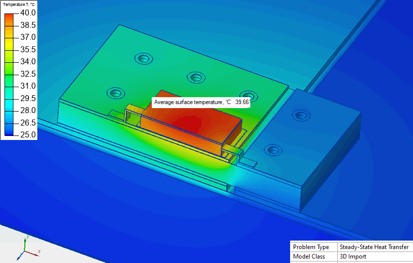
At the bottom the massive heat sink is glued to the aluminum. We consider the bottom side to be at the constant temperature.
In 3D thermal problems QuickField allows to specify only the convection coefficient. To take into account the radiation we use linearization:
The expected chip temperature is T = +40°C. This yields αradiation = 5.8 W/(K·m²). On chip surfaces we specify (α + αradiation) convection coefficient.
Results
Reference:
Engineering question
Set up a 3D QuickField Steady-state Heat Transfer problem for an LED PCB with thermal vias and evaluate temperature distribution from computed field results.
LED circuit boards, metal-core PCBs, thermal via PCB assemblies
Download
Simulation problem
Problem Type
3D problem of heat transfer.
Losses in the LED are 660 mW.
Ambient air temperature is T0 = 25°C, convection coefficient is α = 3.5 W/(K·m²).
Aluminum 138
Copper 390
(Al In Ga N) chip 50
Si 130
Ag-Glue 1.5
FR-4 0.12
MCPSB dielectric 0.6
Calculate the temperature distribution and thermal resistance.
The geometry features symmetry so it is possible to reduce the simulation domain by half.
Radiation heat flux = ε·kSB·(T4 - T04) = ε·kSB · (T³ + T²·T0 + T·T0² + T0³) · (T - T0)
The term αradiation = ε·kSB · (T³ + T²·T0 + T·T0² + T0³) may be considered as an equivalent convection coefficient, where emissivity coefficient is ε = 0.9 and Stefan–Boltzmann constant is kSB = 5.67e-8 W/(m²·K4).
LED temperature is +39°C, so our initial estimation was quite accurate. In case the assumed and calculated temperatures vary considerable we can recalculate the convection coefficient and run the analysis several times till the temperature value converges.
Thermal resistance = Temperature difference / heat flux = (39-25) / 0.66 = 21 K/W.
Material properties and general idea of the example are taken from the paper by Langer, G.; Leitgeb, M.; et al. Advanced thermal management solutions on PCBs for high power applications, IPC Apex Expo (2014) Las Vegas, USA.
Related examples