Solenoid actuator force - QuickField simulation example
This is an example of the solenoid actuator simulation, performed with QuickField software.
How to find solenoid actuator plunger force magnetic field?
Answer Typical applications Geometry
Given
Task
Solution
Results
* Reference: D.F. Ostergaard, "Magnetics for static fields", ANSYS revision 4.3, Tutorials, 1987.
A solenoid actuator is an example of electromechanical transducer, which transforms an input electric signal into a motion. Solenoid actuator, considered here, consists of a coil enclosed into a ferromagnetic core with a moving part - plunger inside. Actuator design requires calculation of the magnetic field and a force, applied to the plunger.
Engineering question
Set up an axisymmetric QuickField DC Magnetics problem for a solenoid actuator and evaluate plunger force and magnetic field from computed field results.
solenoid actuators, electromagnetic plungers, linear electromechanical actuators
Download
Simulation problem
Problem Type
Axisymmetric problem of DC magnetics.
Relative permeability of air and coil μ = 1;
Current density in the coil j = 1 A/mm²;
The B-H curve for the core and the plunger:
Obtain the magnetic field in the solenoid and a force applied to the plunger.
This electromagnetic transducer magnetic system is almost closed, therefore outward boundary of the actuator model can be put relatively close to the solenoid core. A thicker layer of the outside air is included into the actuator model region at the plunger side, since the magnetic field in this area cannot be neglected.
Mesh density is chosen by default, but to improve the mesh distribution, three additional vertices are added to the actuator model. We put one of these vertices at the coil inner surface next to the plunger corner, and two others next to the corner of the core at the both sides of the plunger.
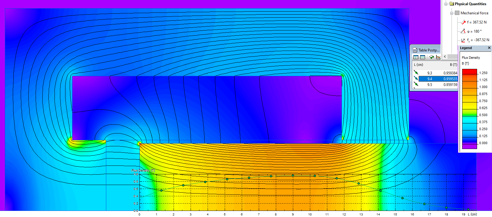
A contour for the force calculation encloses the plunger. It is put in the middle of the air gap between the plunger and the core. While defining the contour of integration, use a strong zoom-in mode to avoid sticking the contour to existing edges.
Flux density in Z-direction in the plunger. The calculated force applied to the plunger f = 374.1 N.
Maximum flux density in Z-direction at the plunger axis
Bz, T
Reference*
0.933
QuickField
0.96
Video
Related examples