Armature winding inductance - QuickField simulation example
This example demonstrates how to calculate the inductance of a single stator phase coil in a permanent magnet synchronous motor.
How to find stator phase winding inductance PMSM?
Answer Typical applications Geometry
Given
Task
Solution
To be able to measure the flux created solely by the energized coil you can turn off magnetization of the rotor permanent magnets and turn off the current in all phase coils but one. But this would cause significant deviation in core saturation from the normal operating point. Which, in turn, would make the calculated inductance value inaccurate.
We solve the problem into two steps:
Results
Engineering question
Set up a plane-parallel QuickField DC Magnetics problem for a stator phase winding and evaluate inductance from computed field results.
PMSM stator windings, synchronous motor windings, phase inductance systems
Download
Simulation problem
Problem Type
Plane-parallel problem of DC magnetics.
Permanent magnet coercive force Hc = 820 kA/m, remanence Br = 1.1 T;
Slot current I = 200 A, number of turns w = 100, three-phase stator winding scheme: A-A, Z-Z, B-B, X-X, C-C, Y-Y
Core permeability μ is given by the B-H curve:
Calculate the phase coil inductance for the normal operating conditions.
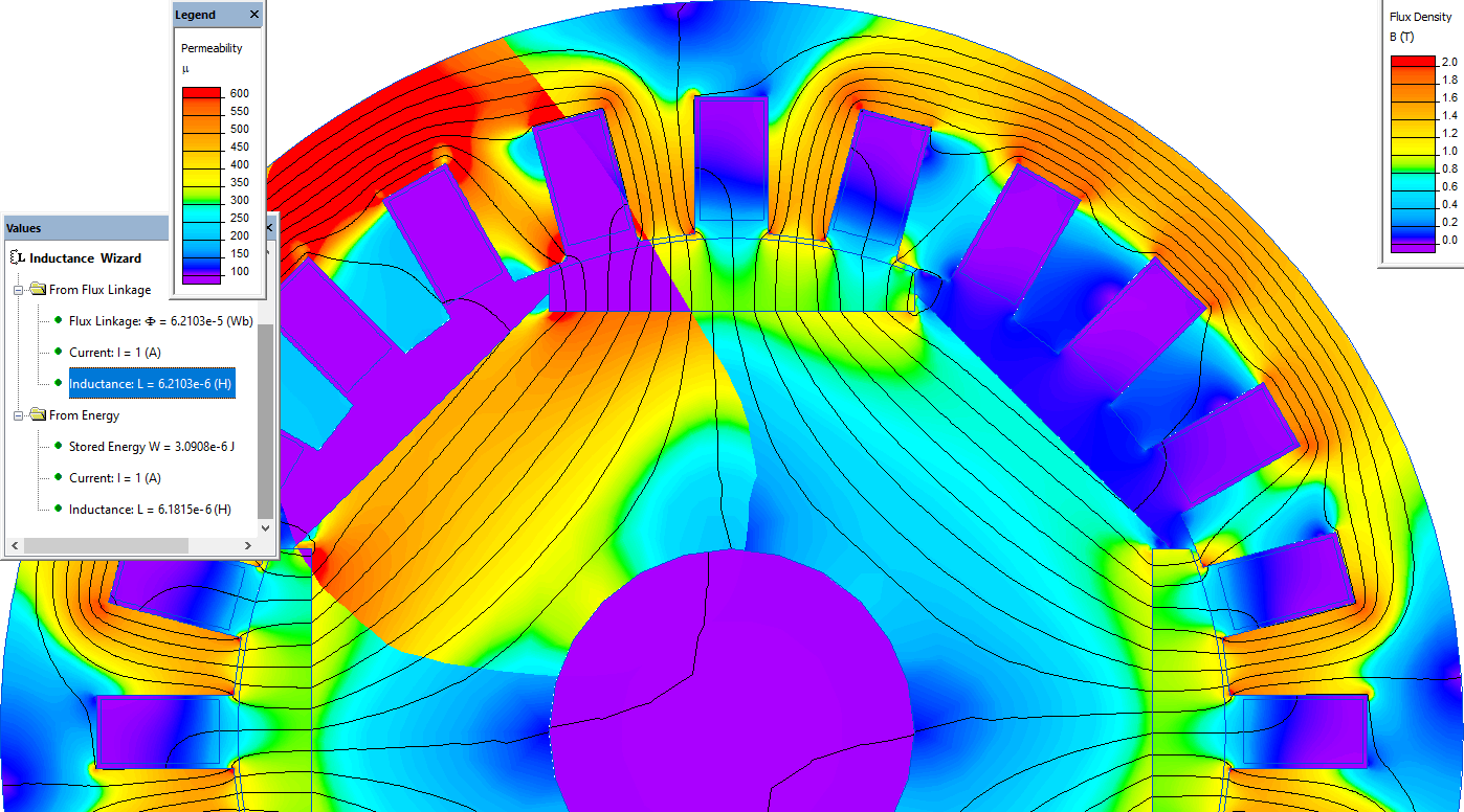
The inductance is the ratio of a magnetic flux to the total current that produced this flux. In case of multi turn winding you should multiply the calculated result by the coil number of turns squared:
Inductance = ( Flux / I ) * w²
Phase inductance is 6.18e-6 * 100 * 100 = 0.0618 H.
Relative magnetic permeability distribution in the steel parts
Video
Related examples