PCB microstrip resistive losses - QuickField simulation example
This is an example of the microstrip line simulation, performed with QuickField software.
How to find microstrip trace AC resistance?
Answer Typical applications Geometry
Given
Task
Solution
Result
Engineering question
Solve the high-frequency AC-magnetic current distribution in the trace and ground return, integrate Joule losses, and obtain AC resistance from the loss power and current.
high-frequency PCB traces, skin-effect conductors, signal integrity conductors
Download
Simulation problem
Problem Type
Plane-parallel problem of AC magnetics.
Copper electric conductivity g = 56 MS/m.
Current I = 1 uA.
AC frequency f = 100 MHz.
Line length Lz = 1 inch.
AC resistance and resistive power loss in a PCB microstrip trace, including current redistribution caused by skin and proximity effects at high frequency.
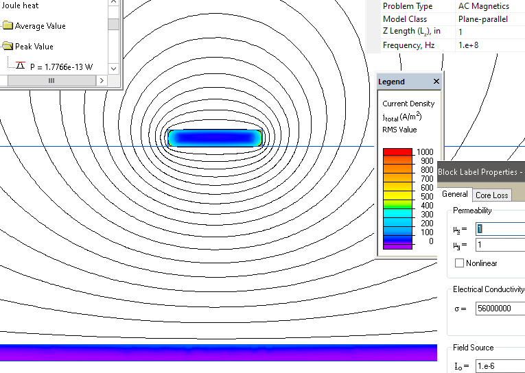
In the trace AC current flows in one direction. The return current flows in the ground plane. QuickField calculates potential drop, current density distribution and Joule losses.
Trace AC resistance R ~ = Losses / I ².
Joule heat losses in the trace 1.77e-13 W (per 1 inch).
Trace AC resistance R~ = 1.77e-13 / (1e-6)² = 0.177 Ohm (per 1 inch).
Current density distribution in the microstrip trace and ground plane
Video
Related examples