PCB line attenuation constant
QuickField simulation example
The shielded transmission line is considered. The line consists of 2 copper strip-like conductors that are rested on the polyethylene substrate. The whole structure, that includes partly an air, is protected by a screen of the complicated geometry.
Problem Type
A plane-parallel problems of AC magnetics and electrostatics.
Geometry
Given
Copper electric conductivity 56 MS/m
Dielectric relative electric permittivity ε = 4
Frequency f = 100 MHz
Current I = 1 A
Task
Find the attenuation constant of the transmission line.
Solution
Attenuation constant of the shielded microstrip-like transmission line is obtained on the basis of the electrostatics and time-frequency analysis.
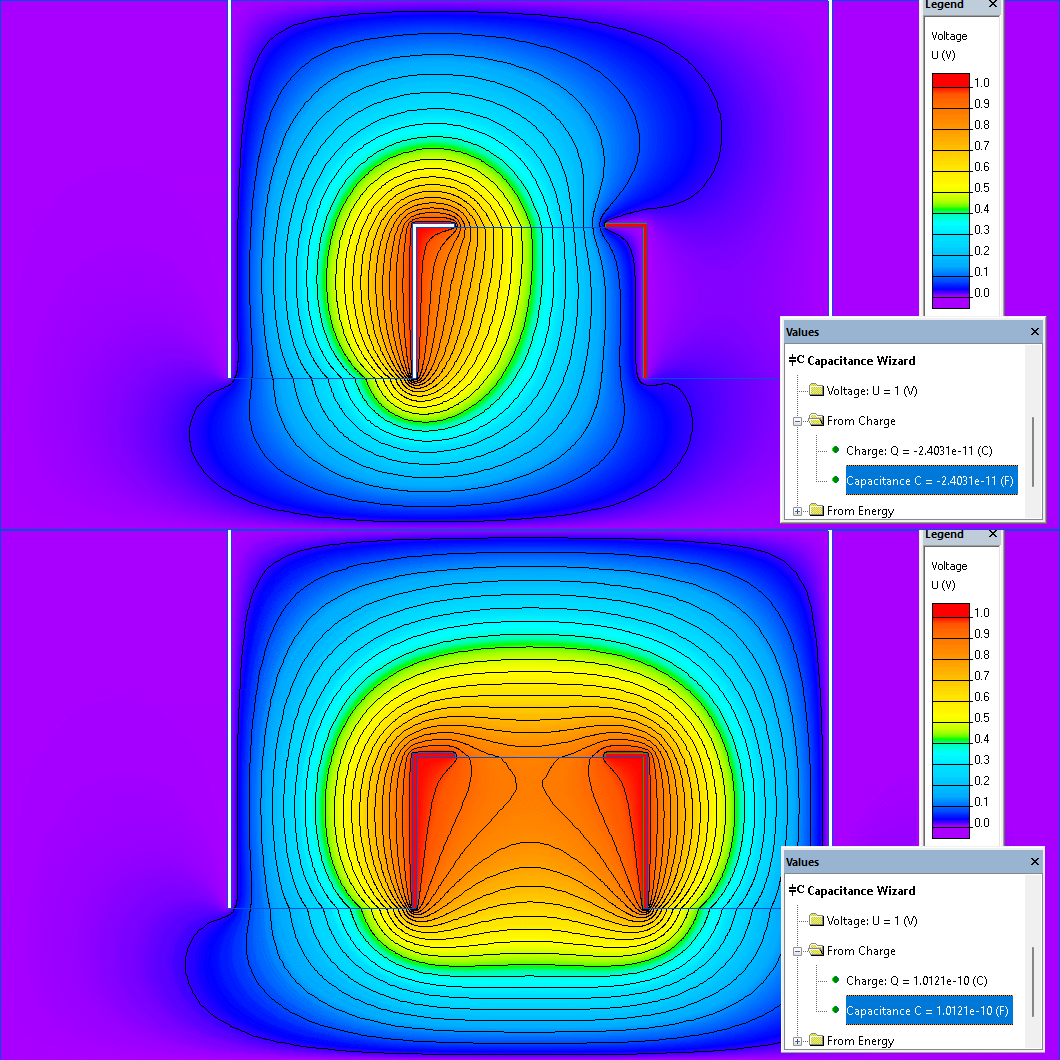
Method of calculation of the characteristic impedance Z0 is based on the calculation of the mutual capacitance C1,2 between two electrodes and mutual capacitance C1,0 between an electrode and a shield.
C1,2 is determined by applying a voltage V on the electrode #2 and a zero voltage on the shield. Then the total charge Q on the electrode #1 is measured, and C1,2 = Q / V [F/m].
Similarly, C1,0 is determined, but in this case both electrodes are placed under voltage V and the shield has a zero voltage.
One has to repeat the previous 2 runs with the only change: a substitution of the dielectric by air (electric permittivity should be assign a value of 1). Thus L1,2 and L1,0 are obtained.
Characteristic impedance Z0 = 2·Z1,2·Z1,0 / (Z1,2 + 2·Z1,0), where
differential impedance Z1,2 = √L1,2 / C1,2
self impedance Z1,0 = √L1,0 / C1,0
Results
Characteristic impedance Z0 = 104 Ohm.
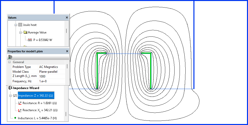
Resistance of the line R = 1.026 [Ohm/m].
Attenuation of the line α = 869·0.5·R/Z0 [dB/100m].
Electric potential distribution in transmission line:

Microstrip transmission line magnetic field:

- View simulation report in PDF
- Download simulation files (files may be viewed using any QuickField Edition).