Solenoid actuator parametric analysis - QuickField simulation example
This is an example of the solenoid actuator simulation, performed with QuickField software.
How to calculate a solenoid actuator's force characteristic, parameter sensitivity, and geometry in one parametric workflow?
Answer Typical applications Geometry
Given
Task:
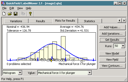
2. Study the current and plunger position influence on mechanical force. Nominal position of the plunger is 10+0.5 cm. Nominal current is 4 A/mm²+10%. With LabelMover Tolerance Analysis we perform variations and calculate the force automatically.
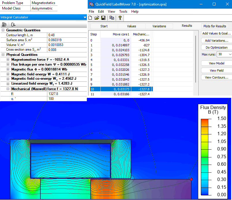
3. Maximize the force. We can maximize the force by increasing the core window size. Thus more coil turns can be added to provide greater force. At the same time the core reluctance increases. Let's find the core window size that provides maximal force.
Results
Engineering question
Use LabelMover for position sweeps, tolerance analysis of current and position, and optimization of core-window height for maximum force.
solenoid actuators, linear electromagnetic drives, industrial actuator mechanisms
Download
Simulation problem
Problem Type
Axisymmetric problem of DC magnetics.
Relative permeability of air and coil μ = 1;
Current density in the coil j = 4 A/mm²;
Core and plunger are made of non-linear ferromagnetic material:
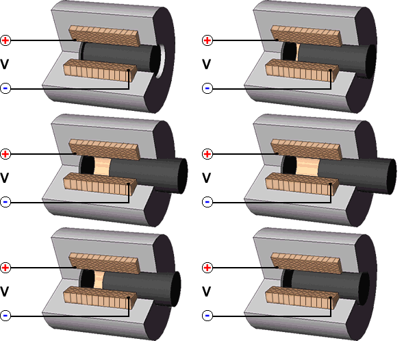
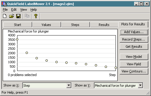
1. Calculate the force vs. position characteristic. The plunger position can vary from 0 to 10 cm. With LabelMover we perform automatic geometry modifications with step of 1 cm. For each step the mechanical force is calculated.
This can be easily done with LabelMover Optimization.
The optimized core window height should be 71.73 mm (initially it was 40 mm).
Video
Related examples