PCB microstrip line equivalent circuit - QuickField simulation example
This is an example of the microstrip line simulation, performed with QuickField software.
How to find equivalent circuit parameters of microstrip line?
Answer Typical applications Geometry
Given
Task
Solution
Result
Engineering question
Set up a plane-parallel QuickField Transient Magnetics problem for a PCB microstrip line and evaluate equivalent circuit parameters from computed field results.
microstrip transmission lines, high-speed PCB traces, planar RF interconnects
Download
Simulation problem
Problem Type
Plane-parallel problem of Transient magnetics.
Line length Lz = 5 inches
Voltage source resistance matches the load resistance and matches the load resistance.
Driver voltage pulse magnitude 2V, pulse duration 5 ns, front 0.25 ns.
Calculate voltage pulse propagation in the matched line.
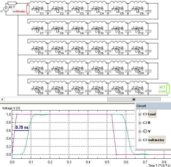
We use line parameters calculated in Microstrip self impedance example to construct electric circuit:
Lumped inductance L = 67 nH, lumped capacitance C = 7.8 pF.
Load resistance Rload = Source resistance Rsource = PCB impedance Z0 = 92.7 Ohm.
We subdivide circuit in n = 30 segments to simulate pulse propagation.
Distributed-element model inductance L' = L/n = 2.23 nH, capacitance C' = C/n = 0.26 pF.
Time delay is 0.75 ns (per 5 inches). Time diagram of signal propagation.
Video
Related examples