Step lap joint
QuickField simulation example
Transformer core is made of standard sized steel plates, insolated by the lacquer layer to minimize the Eddy Current losses. Specific size core manufacturing is achieved by connecting the steel plates lengthwise in the same layer, and adding needed number of lamination layers. One of methods of plates connection is step lap joint. QuickField model allows analyzing the field distribution in the vicinity of the plate joint.
Problem Type
Plane-parallel problem of DC magnetics.
Geometry
Magnetic core is manufactured from the steel plates 12mm x 0.5mm which fill the rectangular cross section 25mm х 6 mm with lacquer insulation 98 μm between the laminated layers. Plates are connected using the step lap joint method.
Given
Core operates with average magnetic flux density about 1.9 T
The B-H curve for the steel core:
Task
Obtain the magnetic field distribution in the core and surrounding air. Find the core areas there performance is deteriorated due to magnetic saturation.
Solution
Magnetic field is specified by current layers at the distances 10 mm up and down from the core surfaces. Operating level of the flux density in the core is produced by the magnetic field stresses of the upper layer 100 kA/m and 0 for the bottom layer.
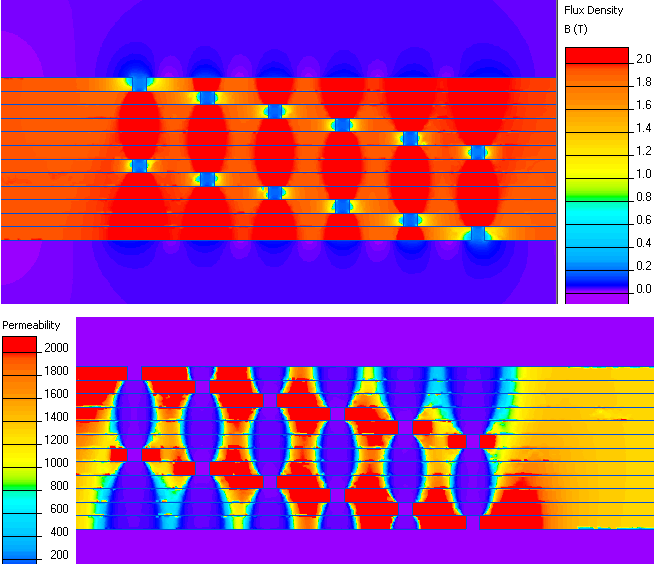
Color maps of the magnetic flux density and magnetic permeability distributions help analyzing the operating conditions of the magnetic core and zones where the magnetic saturation deteriorates the performance of the laminated core.
Results
Pictures below show the color maps of the magnetic flux density, and magnetic permeability (blue color on the magnetic permeability map corresponds to the areas of the saturated laminations). Magnetic field map shows the field 'leaking' near the lamination joints. Average magnetic flux in the core is about 1.9 T.

- Video: Step lap joint. Watch on YouTube
- Download simulation files (files may be viewed using any QuickField Edition).