Transmission line electromagnetic compatibility (EMC) - QuickField simulation example
Two three phase transmission lines go side by side for 10 km. Each transmission line is formed by 3 parallel copper conductors 1 cm diameter each. Conductors are placed on the same height above the ground (flat formation). Conductors are separated by 1 m air clearance. Distance between the nearest conductors of two transmission lines is 18 meters. Left transmission line is energized by three phase currents system.
How to find induced voltage between parallel transmission lines?
Answer Typical applications Geometry
Given
Task
Solution
Results
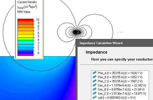
Current density distribution in the soil and induced voltages in secondary transmission line conductors.
Engineering question
Set up a plane-parallel QuickField AC Magnetics problem for parallel transmission lines and evaluate induced voltage from computed field results.
parallel transmission lines, overhead feeders, multi-circuit line corridors
Download
Simulation problem
Problem Type
Plane-parallel problem of AC magnetics.
Left line phase electric current: 250 A (r.m.s.)
Frequency: 50 Hz
Copper electrical conductivity 60 MS/m
Soil electrical conductivity: 0.02 S/m
Transmission line length: 10 km
Find the induced voltages in the right transmission line per 10 km of its length.
In QuickField we should specify peak values of electric current, that is √2 times the root mean square (r.m.s.) value: 250*√2 = 353 А
Measured end-to-end voltages for second transmission line conductors
VA = 22.3 V
VB = 21.0 V
VC = 19.8 V
Video
Related examples