Transmission line inductance matrix - QuickField simulation example
Transmission line consists of three phase conductors A, B, C placed above the earth. The single inductance value is not enough to describe this system. There are self inductance of each conductor and mutual inductance between conductors.
To understand the concept of mutual inductance you can think of some real case scenarios. For example, only phases A and B are energized and phase C is under maintenance and is grounded on both sides. The induced current in the C - ground loop depends on the mutual inductance between the C and other phase conductors.
In this example we calculate the transmission line inductance matrix.
Engineering question
How to find inductance matrix of three phase transmission line?
Answer Set up a plane-parallel QuickField DC Magnetics problem for a three-phase transmission line and evaluate inductance matrix from computed field results.
Problem Type Plane-parallel problem of DC magnetics.
Geometry
Given ACC conductor* consists of 19 aluminum wires with a diameter of 3.447 mm each.
Task Calculate the transmission line inductance matrix.
Solution To measure inductance we energize one of the phase conductors and let the current return through the ground. Flux linkage with each conductor is measured. Then self- and mutual inductance values are calculated: Inductance = Flux linkage / Electric current.
Alternatively, we can measure energies. To measure the self inductance we energize one of the phase conductors and let the current return through the ground.
Inductance = 2 · Magnetic field energy / (Electric current)²
To calculate the mutual inductance we put forth and back current in two of three phase conductors. There is no current in the soil nor in the free phase conductor in this case.
This way the line-to-line loop inductance value is calculated. To convert it to the phase-to-phase mutual inductance the following equation** is used:
Lloop AB = LA + LB - 2·MA-B This yelds MA-B = ½(LA + LB - Lloop AB)
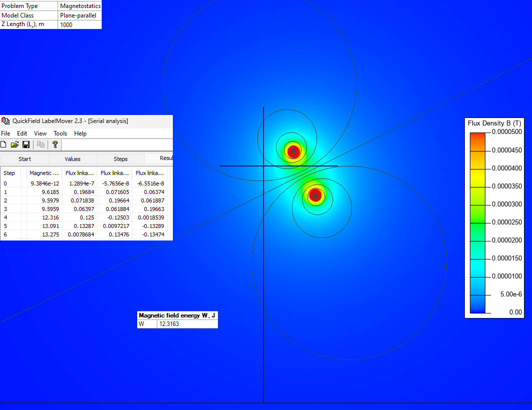
Results Calculations are done per 1 km of the transmission line length. Test electric current value is 100 A.
Inductance = Magnetic flux linkage / Electric current
Energized phase
Measured flux linkage, Wb/km
Inductance values, mH/km
A
B
C
A
B
C
A
0.19684
0.07160
0.06374
1.968
0.716
0.637
B
0.19664
0.061887
1.966
0.618
C
0.19663
1.966
Inductance = 2 * Magnetic field energy / (Electric current)²