Transformer model 2D vs. 3D
QuickField simulation example
Example courtesy of Sergey Chishko
When modeling an electromechanical device, a designer needs to keep in mind that a 2D problem set introduces an error in a field distribution in comparison with a 3D problem solution. However, a solving process of 2D problems is multiple times faster than of 3D. In this example the main (front) and side views of the transformer are modeled to demonstrate that a contribution side view coil sides to the total magnetic flux in the core is negligible.
Problem Type
Plane-parallel problem of DC magnetics.
Geometry
Given
Core relative permeability 1000;
Coil conducts current I = 5 A.
Task
Obtain and compare the values of magnetic flux over the cross section of a transformer leg holding the coil for transformer's front and side view problems sets.
Solution
To study the impact of end effects on the total magnetic flux in the transformer two models are simulated: front view and side view.
Front-view model (2D) considers only a part of a coil with a current direction "in" and "out" of the plane and neglecting end effects of "front" and "end" coil parts with currents flowing along the plane. Side-view (2D) model considers only "front" and "end" coil parts.
Both models features the same number of turns of the coil and the current.
Results
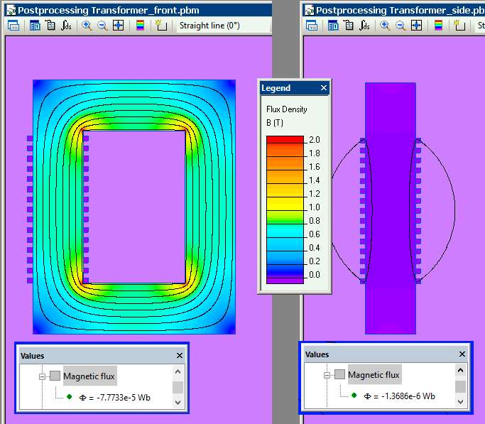
Front-view model magnetic flux is 77.7 uWb (98.3%).
Side-view model magnetic flux is 1.3 uWb (1.7%).
Coil end parts produce only 1.7% of the total magnetic flux and could be neglected in most cases.
Magnetic flux in cross sections of the transformer in front and side models:

- Video: Transformer model 2D vs. 3D. Watch on YouTube
- View simulation report in PDF
- Download simulation files (files may be viewed using any QuickField Edition).