Transmission line electric coupling - QuickField simulation example
Two three phase transmission lines go side by side for 10 km. Each transmission line is formed by 3 parallel aluminum conductors 1 cm diameter each. Conductors are placed on the same height above the ground (flat formation). Conductors are separated by 1 m air clearance. Distance between the nearest conductors of two transmission lines is 18 meters. Left transmission line is energized by three phase voltage system.
How to find electric coupling between parallel transmission lines?
Answer Typical applications Geometry
Given
Task
Solution
We cannot draw insulators in the same 2D model, because they are discrete objects. But insulators may be replaced by distributed grounding resistance. To add the grounding resistance in the model we put the small radius grounded cylindrical electrodes at the axis of the victim line conductors. By adjusting the conductivity σ of the media inside the conductor we may control the leakage current, to be agreed with the known grounding resistance value. Calculation of the required media conductivity is performed in separate QuickField model. Adding of the internal grounding electrode in the conductor also brings the additional capacitance between the conductor and ground, and thus additional reactive leakage currents. In fact AC Electric model already takes into account actual capacitance between the line conductor and ground - they are both present in the field model. The additional internal capacitance thus is extra, and should be set as small as possible to decrease the simulation errors. To eliminate the internal capacitance we set an unphysically small value of the media relative permittivity, ε=1e-20.
Results
Electric field stress distribution in the vicinity of the victim line.
Transmission line conductors are supported by insulators. They have high electric resistance R and the leakage current is rather small, but to accurately simulate the electric fields around transmission line, we should include the grounding circuit and its leakage currents into the field model.
Engineering question
Set up a plane-parallel QuickField AC conduction problem for parallel transmission lines and evaluate electric coupling from computed field results.
parallel transmission lines, overhead feeders, capacitive coupling paths
Download
Simulation problem
Problem Type
Plane-parallel problem of AC conduction.
Left line voltage: 220 kV, r.m.s., line-to-line.
Frequency f = 50 Hz
Transmission line length Lz= 10 km
Insulator resistance R=10 kOhm
Find the electrically induced voltages in the right (victim) transmission line per 10 km of its length.
In QuickField we should specify the peak values of voltages that is √2 times more than r.m.s. value. Also we should recalculate from line-to-line to phase-to-ground voltages following this diagram:
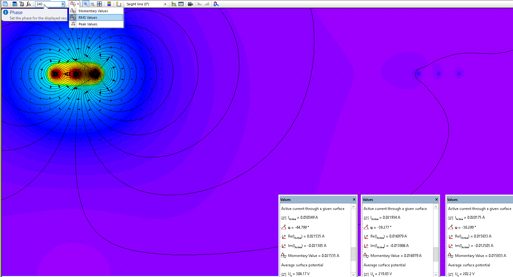
Phase-to-ground electrically induced voltages for victim transmission line conductors
VA = 304 V, VB = 219 V, VC = 202 V
Related examples