Advanced Magnetics--Step-by-Step Description: Step 4
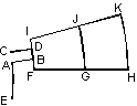
Now we can proceed with defining the geometry itself. Due to existing pattern in the model's geometry, we'll first create a few parts and then use a series of move and copy commands to generate a complete model. Let's start with the coils and steel parts on the stator. Our first goal is to create 1/24 part of the coil structure.
We'll first create edges AB and CD as horizontal line segments, and then rotate them by 7.5 degrees to their normal position. To create these edges we'll need few auxiliary geometric objects, which will be deleted once we find required intersection points.
First we'll create line segment from point (0, 0.375) to point (17, 0.375) and two 180° arcs with radii 12.5 and 14 mm:
-
Use Zoom In to set window dimensions to approximately (0, -20 : 40, 20). This is done for ability to control creation of new points visually.
-
In the Edit menu, click Add Vertices. The dialog box appears, allowing you to create new vertices entering their coordinates from keyboard.
-
Type 0 for x and 0.375 for y, then press ENTER to create a vertex.
-
Repeat the last step for the vertex with coordinates (17, 0.375).
-
Click Close to close the dialog box.