Electrostatics Problem--Step-by-Step Description: Step 4
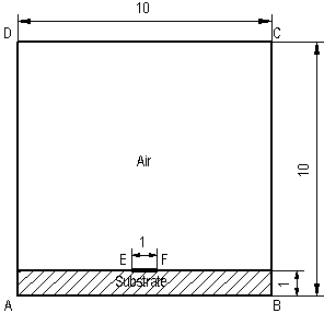
Now we can proceed with defining the geometry itself. To create edges constituting the model boundaries:
-
Press INS (or Insert Mode on Edit menu, or Insert Vertices/Edges on context menu, or corresponding button on the toolbar) to switch Model Editor to Insert mode.
-
Click the left mouse button at (-0.5, 1) and drag to (0.5, 1) to create the edge EF. The edge appears on the screen immediately as you release the mouse button.
-
Repeat 2 at (-5, 0 : 5, 0) for AB, (5, 0 : 5, 10) for BC, (5, 10 : -5, 10) for CD, (-5, 10 : -5, 0) for DA. There is no matter, in which order you create edges, direction of edges also does not matter. If the point you want to click is out of window, use scroll bars to scroll the picture. Don't worry about making mistakes - you can remove erroneous vertices and edges later.
-
Press INS again to cancel Insert mode and return to Pick mode.
If you have created excess points or edges, you can remove them now:
-
Hold CTRL key and pick excess objects with mouse to select them. If you have selected the object you did not want to, pick it again to unselect it. Release CTRL.
-
Press DEL (or Delete Selection on Edit menu or context menu). Deleted objects immediately disappear.
We need some additional constructing to create edges separating substrate from the air. The easy way to create them is to copy the edge AB shifting it 1 cm up. To make a copy:
-
Click the AB edge with right mouse button. The edge is selected and the context menu appears.
-
In the menu, click Duplicate Selection, a dialog box with the parameters for copy operation appears.
-
Click Displacement.
-
In δy box, type 1.
-
Click OK, and then confirm the operation by clicking Yes.
The copy of the line segment AB crosses vertices E and F and produces two new edges separated by these vertices.