3-phase transmission line with grounding - QuickField simulation example
This is an example of the 3-phase transmission line with grounding simulation, performed with QuickField software.
How to calculate conductor currents in a grounded three-phase transmission line?
Answer Typical applications Geometry
Given
Task
Solution
Result
Engineering question
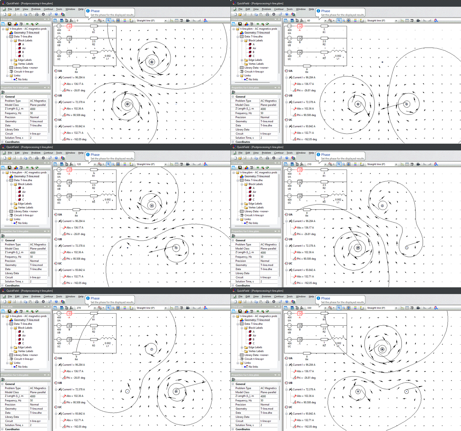
Use equal-magnitude three-phase voltage sources with 0, 120, and 240 degree phase shifts in the AC magnetics model.
overhead transmission lines, HV transmission corridors, transmission line grounding systems
Download
Simulation problem
Problem Type
Plane-parallel problem of AC magnetics.
Line length L = 4 km.
Copper conductor diameter d = 1 mm, conductivity of copper g = 56 MS/m.
Voltage U = 400 V (peak), frequency 50 Hz.
Resistances R_A = 2 Ohm, R_B = 2.5 Ohm, R_C = 1 Ohm;
Inductance L = 0.002 H.
Ground resistance 8 Ohm.
Calculate currents in transmission line conductors.
For three phase system of voltage sources we should specify the same magnitude of the voltage source, but different phase shifts: 0°, 120°, 240°.
Currents: phase A 136A∠-26.8°, phase B 102A∠90.5°, phase C 132A∠-162°.
Video
Related examples