BLDC motor torque ripple - QuickField simulation example
BLDC stands for brushless direct current motor. This type of motor has concentrated windings on the stator supplied by DC current from the controller. At any moment of time only one pair of phase windings is energized.
How to find average torque in BLDC motors?
Answer Typical applications Geometry
Given
Task
Solution
Result
Reference
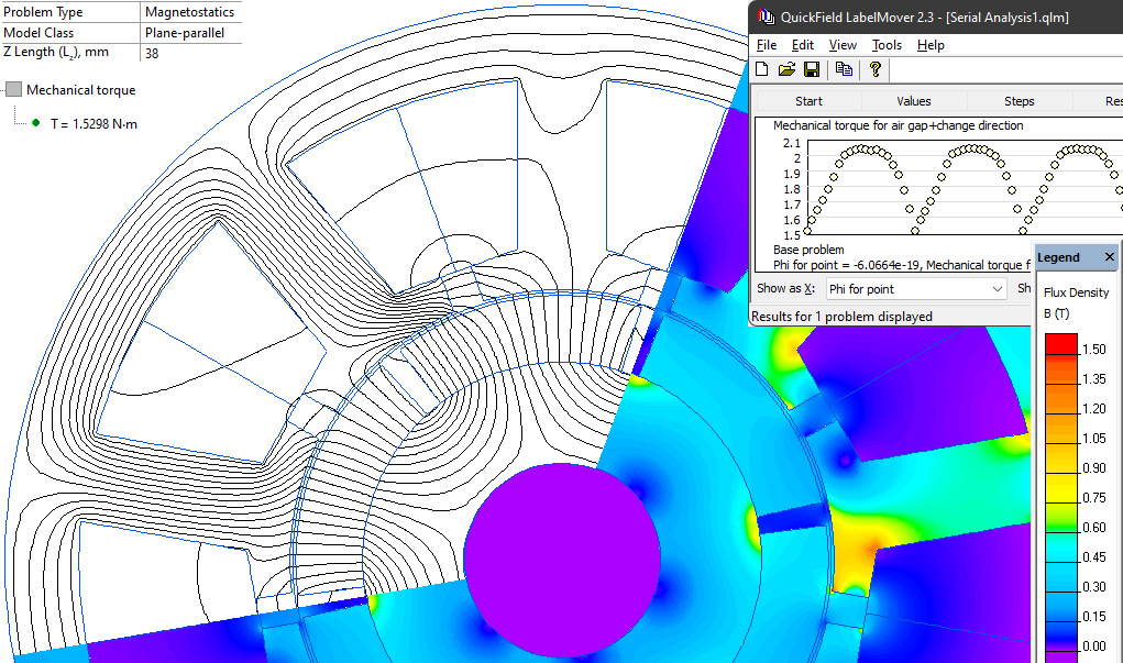
On the geometry model picture you see the moment of time when DC current flows from phase A to phase B, there is no current in phase C.
The torque value depends on the angle between the stator magnetic field and the rotor magnetic field. The rotor rotation is continuous, but the stator winding position is discrete, so the torque value is not constant.
Engineering question
Set up a plane-parallel QuickField DC Magnetics problem for a brushless DC motor and evaluate average torque from computed field results.
BLDC motor windings, brushless motor stators, permanent magnet motor phases
Download
Simulation problem
Problem Type
Plane-parallel problem of DC magnetics.
Motor Z-length is 38 mm.
Magnetic permeability of steel μ = 1000.
Permanent magnet permeability 1.05, remnant flux density 0.4 T.
Rotor pair of poles p = 3.
Current I = 486 A-turns per pole.
Calculate the average torque value.
In a real motor the control system follows the rotor position and commutates the windings to get the maximal torque value. Here we act as a control system. We put the rotor in a proper initial position as shown on the model geometry picture and energy phases A-B. Then we let the rotor run for 20 degrees and switch the windings. Now the phases A-C are energized. The rotor runs for another 20 degrees and again the windings are switched. And so on.
In fact, there is no need to simulate a transient with motion problem. We simulate a set of DC magnetic problems with discrete rotor positions and proper currents in the windings.
To generate and simulate a series of problems the LabelMover parametric tool is used. At each step the torque is measured.
Average torque value is 1.88 N*m with fluctuations between 1.53 N*m and 2.04 N*m.
*Motor dimensions are taken from the book by Nicola Bianchi, Electrical Machine Analysis Using Finite Elements, ISBN 0849333997, example 9.5.
Related examples