BLDC motor slots skewing - QuickField simulation example
Тo reduce the cogging torque and improve the back EMF shape in the brushless permanent magnet motor the stator slots are skewed. We replace the 3D model with a set of 2D model-slices. The no-load mode is simulated. Motor dimensions are taken from this paper [1].
How to find slot skewing effect in BLDC motors?
Answer Typical applications Geometry
Given
Task
Solution
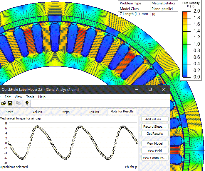
In QuickField we simulate a series of problems with different rotor positions. Torque and the flux linkage are calculated. The flux linkage is calculated for each phase: ΨA+, ΨA-, ΨB+, ΨB-, ΨC+, ΨC-.
Further steps are carried outside of QuickField:
Results
Skewing allows to reduce cogging torque drastically. In the plot you can see torques from straight stators T1, T2, T3, T4 and a torque in a skewed stator (T1 + T2 + T3 + T4)
Flux linkage vs. angle dependency has a triangle shape that results in a trapezoidal shape of back EMF.
Reference:
Engineering question
Set up a plane-parallel QuickField DC Magnetics problem for a brushless DC motor slot geometry and evaluate the slot skewing effect on torque from computed field results.
BLDC stator slot structures, skewed rotor-slot designs, brushless motor laminations
Download
Simulation problem
Problem Type
Plane-parallel problem of DC magnetics.
Motor z-length is 40 mm.
Rotational speed 170 rpm.
Number of turns per slot is 18.
Permanent magnet coercive force 979 kA/m, residual flux density 1.29 T.
Calculate the cogging torque and back EMF in no-load mode.
We represent a skewed stator as a set of straight stators shifted by a fixed angle. Each section is modelled in a separate problem.
LabelMover parameterization tool is used to automate calculations. It automatically modifies the geometry model, solves the problems and extracts the result. We repeat the procedure for each of the straight-stator models.
To measure the cogging harmonics accurately the Δ(angle) value should be small. We take it to be 1/60 of the stator tooth pitch angle.
[1] Jagiela, Mariusz & Mendrela, Ernest & Gottipati, P.. (2012). Investigation on a choice of stator slot skew angle in brushless PM machines. Electrical Engineering. 95. 10.1007/s00202-012-0252-8.
Related examples