Electric circuit analysis - QuickField simulation example
QuickField offers an opportunity to include an electric circuit into the analyzed model. This example demonstrates the accuracy of the embedded circuit simulation.
How to find field-circuit coupling in AC electric circuits?
Answer Typical applications Geometry Given Task Solution Total power is determined as S = U * I' = P + i*Q, Results
Complex power in voltage source V Measured RMS values of voltages and currents, average values of powers.
Power balance
*Mathematical Methods for Physicists. A Comprehensive Guide. 7th Edition. George Arfken, Hans Weber, Frank Harris, p 937-938. ISBN 978-0-12-384654-9.
Engineering question
Set up a plane-parallel QuickField AC Magnetics problem for an AC network and evaluate coupled electromagnetic response from computed field results.
AC electric circuits, coupled circuit networks, educational circuit examples
Download
Simulation problem
Problem Type
Plane-parallel problem of AC Magnetics.
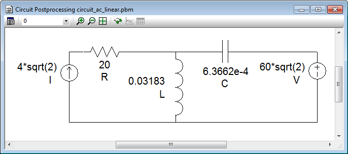
As it is explained in the Solution section below, the field model geometry is not affecting the circuit simulation. Here is the circuit schema.
R = 20 Ohm
XL = 10 Ohm
XC = 2 Ohm
Current source I = 4 A (RMS) @ 0°
Voltage source U = 60 V (RMS) @ 30°
Frequency f = 50 Hz
Calculate currents and voltages in the circuit elements, check the power balance.
QuickField could solve only coupled field-circuit problems, and the field problem should be AC or Transient Magnetic. So we created fictitious AC Magnetic problem with one block, not connected to the circuit, just to agree with this requirement. All following considerations and results relate to the circuit simulation only.
where U - voltage [V],
I' - complex conjugate of current [A],
P - average active power [W],
Q - reactive power [V·Ar].
S(V) = 60@30° * 10.58@(-79.1°) = 634.8@(-49.1°) = 415.6 - i*479.8 [V·A].
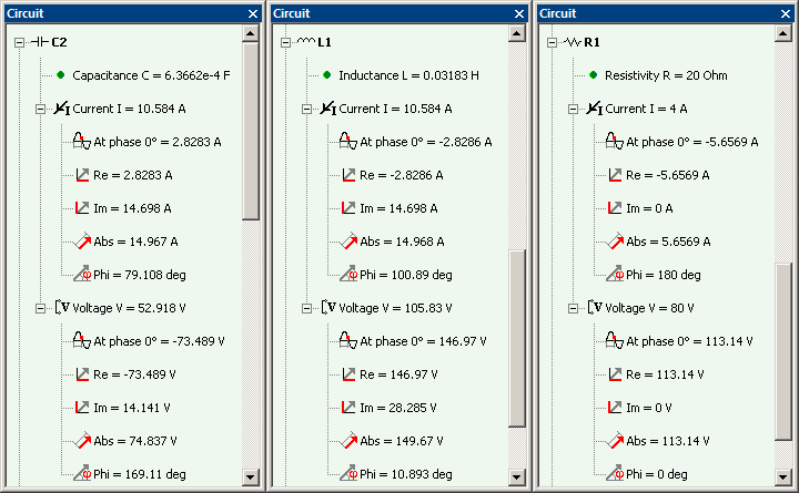
Voltage V, V
Current I, A
Real power P, W
Reactive power Q, V·Ar
R
80 @ 0°
4 @ 180°
320
0
L
105.8 @ 10.9°
10.58 @ 100.9°
0
1119.4
C
52.9 @ 169.1°
10.58 @ 79.1°
0
-559.7
V
60 @ 30°
10.58 @ -100.9°
415.6
-479.8
I
185 @ 6.2°
4 @ 0°
-735.6
-79.9
0
0
Video
Related examples