Cogging torque - QuickField simulation example
Here we will review an example of poor design of the wind turbine generator. Number of rotor poles is chosen to be 2p=12. It turns out that the ratio of the number of stator slots (Z1 = 48) to the number of rotor poles is an integer.
How to find cogging torque in permanent magnet generators?
Answer Typical applications Geometry
Given
Task
Solution
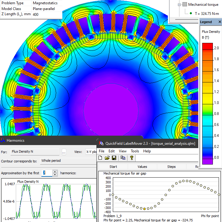
Results
Field picture of the flux density distribution and the fundamental harmonic magnitude.
Reference
Engineering question
Set up a plane-parallel QuickField DC Magnetics problem for a permanent magnet wind generator and evaluate cogging torque from computed field results.
wind turbine generators, permanent magnet generators, slot-pole generator structures
Download
Simulation problem
Problem Type
Plane-parallel problem of DC magnetics.
Axial length is 400 mm.
Stator slots number Z1 = 48
Rotor poles number 2p = 12
Permanent magnet coercive force Hc = 950 kA/m
The B-H curve for the stator and the rotor:
Calculate the cogging torque.
Cogging torque* is a result of permanent magnet magnetic field and the stator core interaction. We do not specify current in the stator armature and measure the torque for a set of rotor positions. The calculations are automated using the LabelMover parametric tool.
Airgap flux density fundamental harmonic is 1.04T. Cogging torque peak value is 324 N*m per 400 mm of the generator axial length.
*Wikipedia: Cogging torque
Video
Related examples