Halbach array generator voltage - QuickField simulation example
The excitation of the magnetic system on the rotor side is due to the Halbach assembly. No-load EMF of a permanent-magnet generator with a Halbach-array rotor, calculated from changing magnetic flux linked with the stator winding.
How to calculate the no-load EMF of a Halbach-array permanent-magnet generator?
Answer Typical applications Geometry
Given
Task
Solution
Result
The caculated EMF is non-sinusoidal. Amplitude of the fundamental harmonic was computed with a harmonic analyzer tool: U1 = 19 V.
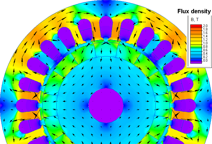
Magnetic flux density distribution in the permanent-magnet generator
Engineering question
Sweep rotor angle, calculate each phase's flux linkage, differentiate it with respect to time, and analyze the resulting EMF harmonics.
Halbach rotor generators, permanent magnet generators, synchronous generator rotors
Download
Simulation problem
Problem Type
Plane-parallel problem of DC magnetics.
Axial length is 50 mm.
Stator phase coil number of turns w = 90,
Coercive force of permanent magnets 730 kA/m,
Rotor poles 2p = 4,
Synchronous rotation speed n = 750 rpm.
Calculate the idle generator electromotive force (EMF).
In no-load there is no electric current in the winding, the output voltage is equal to the induced electromotive force.
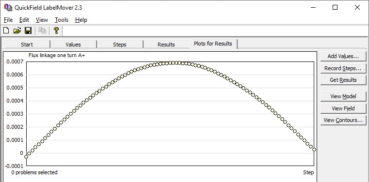
First in QuickField we measure the flux linkage with half-coils Φ_A, Φ_a, Φ_B, Φ_b, Φ_C, Φ_c as a function of rotor angular position. We get this dependency automatically using the LabelMover parametric calculation utility. Then the phase winding flux linkage is calculated: Φ_Aa = Φ_A-Φ_a, Φ_Bb = Φ_B-Φ_b, Φ_Cc = Φ_C-Φ_c.
The electromotive force is calculated as the ratio of the flux linkage increment ΔΦ to the angle increment Δφ:
EMF = -w * dΦ/dt = -w * ΔΦ / (Δt), where time increment is related to the angle increment Δφ as: Δt = (Δφ/360) / (n/60).
In LabelMover we set the angle increment to be Δφ = 1 degree. The time required to rotate the rotor by 1 degree is Δt = (1/360) / (750/60) = 2/9 ms.
Video
Related examples