Induction motor - QuickField simulation example
The motor consists of the stator with the three-phase winding and a rotor. Ferromagnetic rotor body has 36 slots filled with the aluminum. These slots are all connected by the ring on the front and back side. Our task is to calculate the torque acting on the rotor as a function of rotor speed.
How to find torque-speed characteristics of three-phase induction motors?
Engineering answer Typical applications Geometry
Given
Task
Solution
Torque is a result of rotor cage eddy currents interaction with the stator magnetic field. To calculate torque at zero speed we draw model as is with motionless rotor. At synchronous speed there is no eddy currents in the rotor cage. We can model this by specifying zero conductivity of rotor cage.
To automate torque vs. speed calculation we use LabelMover parametrization tool. We change rotor conductivity incrementally and measure input current and rotor torque. Each conductivity value corresponds to some rotation speed.
Results
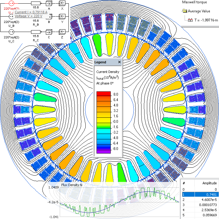
Field picture of the eddy currents in the rotor cage and flux density distribution in the air gap at rated speed calculated in QuickField.
Engineering question
Set up a plane-parallel QuickField AC Magnetics problem for a three-phase induction motor and evaluate torque-speed characteristics from computed field results.
three-phase induction motors, squirrel-cage motors, industrial AC motors
Download
Simulation problem
Problem Type
Plane-parallel problem of AC magnetics.
Frequency f=50 Hz, synchronous rotation speed 1500 rpm.
Stator slots number Z1 = 48, number of wires in a slot is w=100, wire cross-section area is 0.125 mm², copper electric conductivity at 70°C is σ1 = 46.8 MS/m
Rotor slots number Z2 = 36, slot cross-section area is 22.2 mm², aluminum electric conductivity at 70°C is σ2 = 31.1 MS/m
Number of phases m=3, phase voltage U = 220 V (r.m.s)
Calculate current and torque as a function of rotation speed.
The 2D geometry model includes only the in-slot part of the coil. The overhang part is not present. The overhang conductors' resistance R is added to external electric circuit.
R = (1/σ1) * Total length / Wire cross-section area = (1/46.8e6) * 88 / 0.125e-6 = 15 Ohm,
where Total length = overhang length (front + back sides) * Number of turns in phase coil = (55mm + 55mm) * 800 = 88 m.
For non-zero roation speed n we should attenuate rotor cage conductivity as: σ2 * ( 1 - n/synchronous speed )
Maximum efficiency of 84% is achieved at the speed of 1447 rpm. Rated current is 0.79 A.
Rotor bar conductivity, MS/m
Rotation speed = synchronous speed * (1-Rotor bar conductivity/σ2), rpm
Torque, N*m
Power on shaft = (Rotation speed*2π/60) * Torque, W
Phase A current
Power factor = cos(Phase current angle)
Input power = 3* Voltage * Phase current magnitude * Power factor, W
Efficiency = Power on shaft/ Input power
0
synchronous speed
1500*(1-0/31.1e6) = 1500
0
(1500*2*3.142/60)*0 = 0
0.64A ∠-83.3°
cos(-83.3°)=0.12
3 * 220 * 0.64 * 0.12 = 50.6
0/50.6 = 0
31.1e6
stall
1500*(1-31.1e6/31.1e6) = 0
6.14
(0*2*3.142/60)*6.14 = 0
4.79A ∠-19.2°
cos(-19.2°)=0.94
3 * 220 * 4.79 * 0.94 = 2970
0/2970 = 0
1.09e6
1500*(1-1.09e6/31.1e6) = 1447
2.0
(1447*2*3.142/60)*2.0 = 303
0.79A ∠-46.6°
cos(-46.6°)=0.69
3 * 220 * 0.79 * 0.69 = 360
303/360 = 84%
Video
Related examples