Inductive sensor - QuickField simulation example
Inductive position sensor is based on a principle of measuring the electric voltage on the resistor in the circuit with variable inductance, which depends on the mutual position of the sensor components.
How to find inductance variation in inductive position sensors?
Answer Typical applications Geometry
Given
Task
Solution
Result
Engineering question
Set up a plane-parallel QuickField AC Magnetics problem for an inductive position sensor and evaluate inductance variation from computed field results.
inductive position sensors, variable inductance sensors, displacement sensing coils
Download
Simulation problem
Problem Type
Plane-parallel problem of AC magnetics.
The number of turns in the coil N = 210
AC voltage frequency f = 400 Hz
Source voltage U = 24 V (root mean square)
Load resistor R = 1 Ohm
Air gap 0.1 - 0.6 mm.
Calculate the voltage across the load resistor of the sensor as a function of the air gap size.
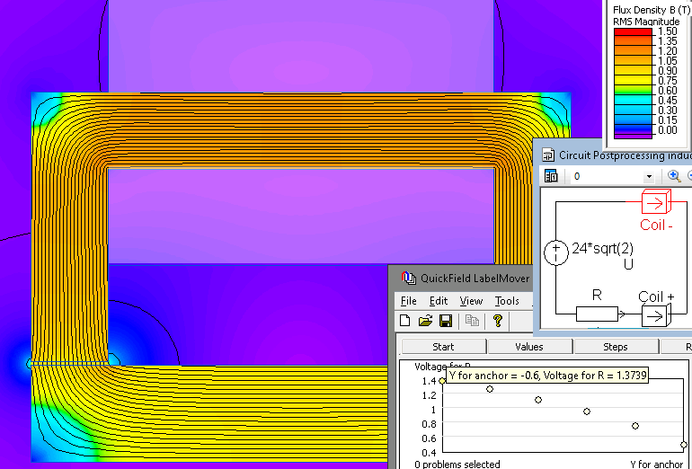
When the position of the rotor changes, the inductance of the coil changes. The joint simulation of the magnetic field and the electric circuit is performed.
In the electric circuit, the amplitude value of the source voltage must be specified, i.e. U * sqrt (2).
To automate the calculations, the LabelMover add-in is used, which moves the rotor by 0.1 mm increments, solves the problem and measures the voltage drop across the load resistor.
Magnetic flux density distribution in the core, electrical circuit with load resistor and output voltage for various air gap sizes.
Related examples