Linear induction motor - QuickField simulation example
This example is prepared by the Metropolian Hyperloop Design Team participating in the Hyperloop Global competition in May 2024.
How to find linear induction motor thrust force versus speed?
Answer Typical applications Geometry
Given
Task
Solution
We are going to reproduce 2 experiments that you can do with the real motor: a synchronous motion speed regime and a locked rotor regime.
Unlike real experiments we have all field parameters readily available.
Results
Fixed rotor regime current Is = 20 A (r.m.s).
Reference: Induction motor, Wikipedia.
To be able to include the motor into the circuit simulator it is necessary to calculate electric motor equivalent circuit parameters. A no-load mode test and the fixed rotor test are carried out to calculate these parameters.
Engineering question
Set up a plane-parallel QuickField AC Magnetics problem for a linear induction motor and evaluate thrust force versus speed from computed field results.
linear induction motors, transport propulsion motors, electromagnetic drive systems
Download
Simulation problem
Problem Type
Plane-parallel problem of AC magnetics.
Z-length is 70 mm. Slot dimensions are 20*85 mm. Number of slots is 25.
Rail is made of Aluminum 6061-T6 with electrical conductivity of σ = 35 MS/m.
Number of conductors in the slot is 24, current is 20 A (r.m.s). Frequency f = 50 Hz.
Magnetic permeability of the stator is 1000.
Calculate the equivalent electric circuit parameters.
The resistance of the stator windings can be calculated from the winding geometric dimensions as Rs = resistivity * Length / Conductor cross-section. We do not calculate it here.
In this example we only calculate the resistance caused by the losses in the rotor and the inductance.
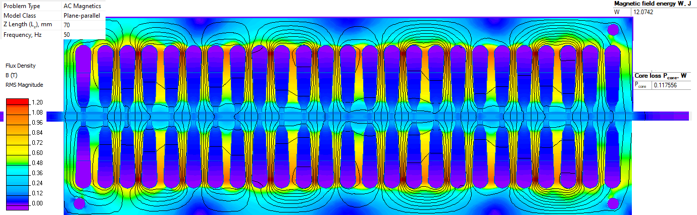
First we simulate the synchronous speed regime (slip value s=0). In this regime there are no eddy currents in the rotor as the rotor speed is equal to the speed of the magnetic field produced by the stator winding. We model this by specifying zero conductivity of the rotor.
Then we simulate a locked rotor regime.
The inductance is the ratio of the magnetic field energy doubled to the electric current value squared: L = 2*W / I²
The resistance is the ratio of the active power to the electric current value squared: R = P / I²
No load regime current I = 20 A (r.m.s). Magnetic field energy is 12.0 J. Inductance Leq = 2*12.0 / 20² = 0.06 H, reactance X = 2*π*f*Leq = 18.85 Ohm.
Core loss Pcore = 0.117 W. Resistance Req = 0.117/20² = 0.0003 Ohm.
Joule heat in the rotor is 2293 W, equivalent resistance Req = 2557/20² = 6.39 Ohm.
Magnetic field energy is 15.0 J. Inductance Leq = 2*15.0 / 20² = 0.075 H, reactance X = 23.6 Ohm.
Related examples