Turbine generator synchronous inductance - QuickField simulation example
The magnetic reluctance of the rotor varies along its d- and q-axes. As a result, stator armature inductance varies with the rotor angular position. When the rotor d-axis is parallel to the stator magnetic field, the inductance value is maximum and is referred to as synchronous inductance.
How to find synchronous inductance versus rotor position?
Answer Typical applications Geometry
Given
The B-H curve for the rotor and stator yoke:
Task
Solution
Results
Engineering question
Set up a plane-parallel QuickField DC Magnetics problem for a synchronous machine and evaluate inductance versus rotor position from computed field results.
synchronous machines, rotor saliency systems, synchronous motor windings
Download
Simulation problem
Problem Type
Plane-parallel problem of DC magnetics.
Axial length is 5400 mm.
The B-H curve for the tooth zone:
Calculate phase coil inductance.
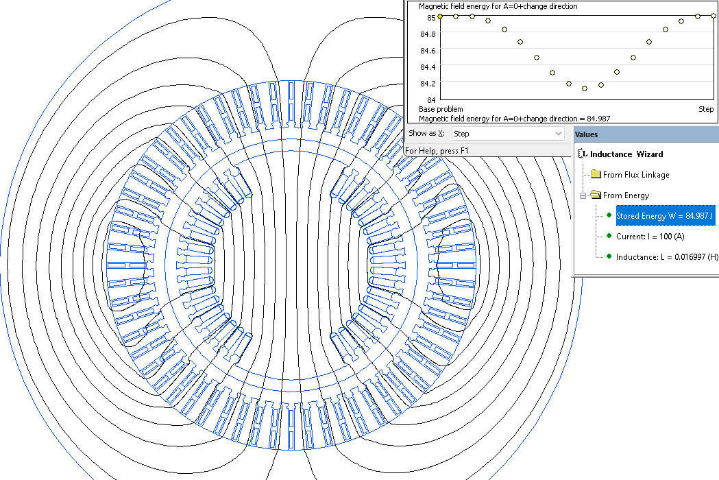
Only the A-X coil is energized by direct current to calculate a phase coil inductance. The magnetic field energy is measured:
Inductance = 2* Energy / Current²
To obtain the maximum inductance value, we solve a series of problems with varying rotor angular positions.
A LabelMover parameterization tool is used to automate the generation and analysis of a series of problems.
Synchronous inductance Ld = 0.017 H.
Video
Related examples