Synchronous machine power-angle curve - QuickField simulation example
The main characteristic of a synchronous motor is the electromagnetic torque vs. load angle dependence. In synchronous machines the rotor and the stator magnetic field rotate with the same angular velocity. The load angle is measured between the rotor position and stator magnetic field. Without mechanical loading the load angle is zero - the rotor is always aligned with the stator field. As the mechanical loading increases, the rotor begins to lag behind the stator field and load angle increases.
How to find power-angle curve of synchronous motor?
Answer Typical applications Geometry
Given
Task
Solution
Result
We are going to simulate a simplified case. The power angle is predifined and the current in the stator winding is predifined. The task is to find a torque.
Engineering question
Set up a plane-parallel QuickField DC Magnetics problem for a synchronous motor and evaluate power-angle characteristics from computed field results.
synchronous machines, generator load angle systems, stability characteristic studies
Download
Simulation problem
Problem Type
Plane-parallel problem of DC magnetics.
Machine z-length is 65 mm.
Phase current density j = 3 А/mm²
Coercive force of NdFeB permanent magnets Hc = 730 kА/m
Power angle δ = 30° (electrical degrees).
The B-H curve for the stator and the rotor:
Calculate the average torque.
Due to stator slotting the torque momentary value depends on the rotor position. To calculate the averge value we should simulate a series of problems with different rotor positions and appropriate momentary values of the current in the stator winding.
We assume that the rotor rotates in synchronism with the stator field. Hence the electromagnetic torque does not change with time.
To measure the torque you should specify momentary values of winding currents j*cos(phase angle) and set the rotor in proper position. For this analysis it doesn't matter whether the rotor or stator is rotating. It is convenient to rotate the stator relative to the rotor. Otherwise, when the rotor is rotated, the permanent magnets coercive force direction should have to be adjusted for each relative position
To automate the solution of a series of problems, it is convenient to use the LabelMover utility, which will automatically change the model and measure the electromagnetic torque.
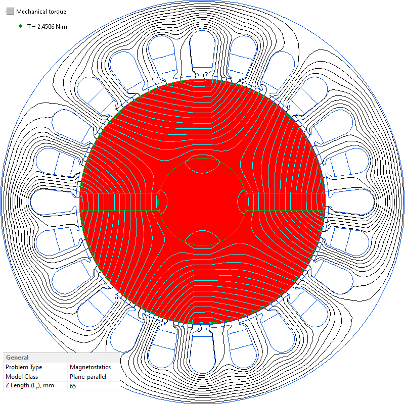
Magnetic field distribution and torque calculation for the load angle of 30 electrical degrees.
Video
Related examples